To pump negative ions into the air is a contorversely discussed method to improve you inhouse
atmosphere. I don't know and won't comment on the true effect of this method, but anyway
you can use this project for other purposes too, where you need a high impedance (=low current)
voltage source of some kilovolts.
So don't miss this warning!!!
![]() The voltages and currents in the equipment
described on this page are most probably not lethal but at least unpleasant if it is
used improperly. I cannot be held responsible for any damage
that occurs due to information available on these pages.
The voltages and currents in the equipment
described on this page are most probably not lethal but at least unpleasant if it is
used improperly. I cannot be held responsible for any damage
that occurs due to information available on these pages.
![]() Be sure to take all necessary precaution
when operating similar equipment and keep a safe distance
to the high voltage parts.
Be sure to take all necessary precaution
when operating similar equipment and keep a safe distance
to the high voltage parts.
![]() When operating high-volatage equipment with
open discharges, large quantities of ozone can be produced. Make sure to have sufficient air flow.
When operating high-volatage equipment with
open discharges, large quantities of ozone can be produced. Make sure to have sufficient air flow.
![]() Capacitors on the high-voltage
side can keep their charge for quite a while after the power supply has been switched off. Be sure to discharge
the high-voltage side properly before touching any of its parts.
Capacitors on the high-voltage
side can keep their charge for quite a while after the power supply has been switched off. Be sure to discharge
the high-voltage side properly before touching any of its parts.
1. Function
2. Construction
3. Pictures
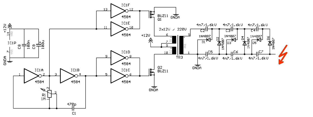
The basic part of this project is a resonant low-voltage DC powered voltage converter. A standard
mains transformer is used backwards, i.e. supplying an alternating current into the low-voltage
secondary coils and transforming this voltage level up to a high-frequency AC voltage which is
then rectified in a three stage cascade multiplier.
The transformer used in my prototype is a 240V/2x12V, 1.5VA type printed circuit board transformer.
The middlepoint of the two secondary windings is connected to the low-side supply voltage of 12V, while
the other ends of the secondary coils are alternating connected to ground by two power MOSFETs.
The gate voltage for the MOSFETs is directly derived from each two parallely coupled CMOS inverters
by thus using only one chip for the oscillator and driver circuitry. The frequency is derived from
an RC oscillator build by two CMOS Schmitt trigger inverters, a timing capacitor and a trimmable
resistor for frequency adjustment.

Schematic of the high-voltage supply of the air ionizer.
(click on the image to view it in full size)
The circuit of the high-voltage air ionizer consists of 3 parts
1. RC oscillator and power driver
2. high-voltage cascade multiplier
3. ion generator
I'm going to describe each of the parts in more detail now.
1. RC oscillator and power driver
The RC oscillator used here is quite simple and a very usable circuit. It uses two CMOS
inverters with Schmitt trigger input characteristics (using "normal" inverters results in
asymmetric square wave output with a duty cycle different from 50%). The oscillation
frequency is determined by the RC time constant of the timing capacitor and resistor, using
a variable resistor of up to 1MOhm and capacitors from 100pF up to several 10µF a wide
range of freqeuncies can be covered. The output of the first and second inverter show a
180 degree phase shift and are fed into each two further inverters which are used as
decoupling buffers driving the large gate capacity of the power MOSFETs (typically 1000pF).
As the gate signals of the two power MOSFETs are in antiphase, always exactly one of them is in
the conducting state driving current through one winding of the transformer.
The whole circuit shows a resonancy where the voltage on the high voltage side reaches a
maximum. Using the given type of transformer and dimensions of the cascade, this frequency is
approximately around 15kHz. As the MOSFETs are operated far below their critical values, no additional
cooling is needed.
2. high-voltage cascade multiplier
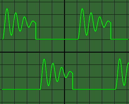
On the high-voltage side of the transfomer, a high voltage is induced. Looking at the oscillogram of the drain voltages
of the power MOSFETs you'll see, that even there a voltage significantly higher than the 12V supply voltage
occurs due to self induction and cross induction from the other driven winding. Providing a large
transient dI/dt on the low voltage side, the AC high voltage is higher than the perhaps expected
220V from the windings of the transformer...
The six capacitors and diodes in the three stage cascade work as a charge pump. By turning all diodes
around in their direction the output of the cascade would be a positive DC voltage instead of negative as in the
presented design. By exchanging the switching diodes with faster ones, the efficiency could
increase. This part of the circuit should be build up with good isolation otherwise creeping currents
will consume most of the generated power. Avoid sharp points on the circuit board and soldering points
as these would give rise to an increased electrical field and possible leakage. The open circuit
voltage in my setup is somewhere around 4kV, but even when probing with a 50MOhm impedance high voltage
probe, the measured voltage decreases to about 2kV. From this the impedance of the cascade can
be estimated to 50MOhm and the maximum output current to below 80µA.
!!! WARNING !!!
The drain of the MOSFETs is connected to the metal tab of the TO-220 package. As
you can see from the oscillograms below, the drain voltage under operation is much higher than the operating voltage.
NEVER touch the MOSFET package under operation!!!
3. ion generator
What to do with the high voltage generated by the cascade? By generating a high field e.g. at
a sharp point or wire end, a sensable wind of ions can be generated emerging from this pin point.
The high-voltage potential can be adjusted by driving the circuit at a frequency slightly
below or above the resonancy. Driving it under resonancy might actually give a too high voltage
for the use as negative ion generator which will result in the production of some amounts of ozone
(it smells a bit like chlorine and should be avoided). You can find the actual resonant frequency by
monitoring the DC current going into the circuit from the 12V power supply. It peaks at the resonancy with
a value of about 40mA depending on the transformer used.
An effective ion generator can be build by spreading the single leads in a multilead wire
into the air and connecting the other end to the top point of the cascade. In a distance of about 1cm
a guard ring connected to the ground level can be installed. Powering on the circuit you should
be able to feel a faint wind coming from this assembly and in the dark you might see small blue
lights at the ends of the wires.
| Partlist | ||||
|---|---|---|---|---|
| C1 | 470pF | timing capacitor | ||
| C2-C7 | 4700pF/1600V | ceramic high-voltage capacitors | ||
| C8 | 100nF | |||
| C9 | 100µ/25V | |||
| D1-D6 | 1N4007 | or faster diodes Vbr>1000V | ||
| IC1 | 4584 | hex Schmitt trigger inverter | ||
| Q1 | BUZ11 | Vds=50V, Id=30A, Ron=0.04Ohm | ||
| Q2 | BUZ11 | Vds=50V, Id=30A, Ron=0.04Ohm | ||
| R1 | 1M | trimmable resistor | ||
| TR1 | 240V/2x12V, 0.75VA each | standard PCB mounted type | ||

Oscilloscope image of the drain voltages of both power MOSFETs under operation.
(click on the image to view it in full size)
- soon to come -
Responsible for these pages: U. Zimmermann