You might have seen those toys were a fancy sculpture magically
swings and moves, obviously driven by thin air. Or you might
have seen the very first electronic watches, pupular until the
quartz resonator appeared on the market in the late 1950s.
The principle behind is always the same: a small electromagnet
kicks the weight of a pendulum just a bit during every period,
compensating for friction losses.
1. History
2. Function
3. Construction
4. Operating
5. Pictures
Everything that moves looses energy due to friction. When Galilei discovered the
physical law of the pendulum and clock makers started to adapt the
precise oscillation period of a swinging mass, a lot of inventions
had to deal with the replentishment of the friction losses. Either
weights or springs had to be pulled in order to secure the working
of large and small clocks.
With the discovery of electromagnetism a new method came up. Small
electromagnets were switched on, triggered by the pendulum, to just for
a short instance either kick or drag the pendulum and thus transfer
a small amount of energy to the system. Using transistors these became
the very first electronic clocks and watches, pioneered by companies like
Hako or Junghans and inventors like Fedorow.
A small permanent magnet has to be mounted at the end of the pendulum,
just opposite to the fixed mounted coil which serves as an electromagnet.
In order to switch the electromagnet in exactly the right moment to "kick"
the pendulum, some feedback from the pendulum to the electronics has to be provided.
Using a second winding on the same core as the electromagnet gives
access to the induced current by the magnet when the pendulum passes
the center of the coil. This signal current is the amplified by the transistor
and fed back into the electromagnet which in turn produces a field which deflects
the permanent magnet and thus transfers energy to the pendulum.
Schematic of the pendulum drive, see text for details.
(click on the image to view it in full size)
| Partlist | ||||
|---|---|---|---|---|
| C1 | 100nF | |||
| C2 | 20µF/16V | |||
| Q | BC549C | ß=600 | ||
| R1 | 1.5M | defines the working point and power consumption typical values 1M-10M depending on battery voltage | ||
| R2 | 2.2k | depending on L1 series resistance 470<R2<10k | ||
| L1 | 1000 windings, 4mm core dia 0.1mm Cu wire 80 ohms | |||
| L2 | 1000 windings, 4mm core dia 0.1mm Cu wire 80 ohms | |||
The circuit of the pendulum drive consists of 3 parts
1. induction coil L1, R2
2. transistor Q and DC bias network R1, C1
3. electromagnet L2
1. The induction coil
gives the feedback signal to the base of the transistor. It is wound onto the
same core as the electromagnet and senses the movement of the field
of the pendulum's magnet through the core of both inductors. Since
it only conducts the small induced current it can be wound from very thin
wire, in order to simplify the design you can also use the same type of
wire as for the electromagnet. As the coil is also exposed to the
field generated by the electromagnet, there is a tendency to oscillations.
If the series resistance of the coil L1 is too low, an additional
resistor dampens those oscillations.
2. The transistor
switches the current through the electromagnet L2depending on the
signal from L1. In "standby" a constant base current is flowing
from the positive supply through R1 into the transistor,
giving rise to a standby current through the electromagnet connected between the
emitter of the transistor and ground. The polarity of the permanent magnet and
the current through the electromagnet should be chosen to result in a deflection
of the pendulum from the electromagnet when the sense coil is not connected to
the base of the transistor.
The working point of the transistor is determined by the supply voltage and the
base resistor R1
Ib=(Vbat-Vbe)/R1=(2.5-0.6)/1.5M=1.2µA
Ic=I(L2)=ßIb=760µA
The overall power consumption of the circuit is dominated by the standby current. Using the values above the circuit will run continously for about 1/4 year from 2 NiMH AA cells.
First you should check the dc mode of operation. Connect all parts according
to the schematic but don't yet connect L1 to the base of the transistor through C2.
After connecting the supply voltage you should be able to measure the base-emitter voltage
of the transistor as well as the voltage drop over the coil L2.
Once C2 has been charged through the large resistor R1, you can measure
a Vbe of about 0.6V. If you have measured the
dc resistance of L2 you can determine the emitter current through the
transistor from the voltage drop over the coil and thus measure
the total current consumption of the circuit.
The easiest way to find the right polarity of the coils is the use of
an oscilloscope. Here you can follow the signals at the base and emitter
of the transistor. If the signals look like the oscillograms below when
moving a magnet over the coil, everything is fine and ready to use.
Oscillogram of the induced voltage in the sense coil (measured over both the coil and the resistor R2, upper red curve)
and the corresponding voltage drop over the electromagnet L2 (measured between emitter of Q and ground, lower blue curve).
10:1 oscilloscope probes were used thus the amplitude of the base signal (red) is 400mVpp and
the amplitude of the emitter signal is 2.25Vpp.
(click on the image to view it in full size)
Oscillogram over a sequence of 4 passages of the pendulum over the core, hence 2 full oscillation periods of the pendulum.
(click on the image to view it in full size)
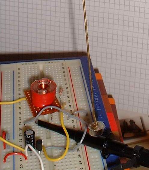
An experimental prototype of the pendulum drive mounted on a small breadbord. The pendulum consists of a small permanent magnet glued to a 35cm
long brass stick.
(click on the image to view it in full size)
Responsible for these pages: U. Zimmermann