Most of today's personal computers are equipped with quite advanced soundcards. These soundcards often contain powerful analog/digital converters, able of up to 100 ksamples per second at 16 bit or more. Why not use this capability and build a digital storage oscilloscope around it...?
1. History
2. Function
3. Operating
When using the soundcard as an oscilloscope, the low input impedance
is a large disadvantage. Not only would it influence the measured circuit
and possibly shortcircuit low input signals. It also would not allow the usage
of commercial oscilloscope probes which normally are designed to work with
oscilloscope inputs with a typical impedance of 1 Mohm.
Using a 10:1 oscilloscope probe at a typical soundcard input with an impedance in the order
of 1 kOhm would give an attenuation of 10000:1 instead and since
the impedance of most soundcards is not even known to the user, a complicated
calibration would be necessary.
The bandwidth of the oscilloscope is limited to at max half
the sample frequency, i.e. to audio signals below approx. 20kHz for
a standard sound card. Since the signals are ac coupled,
the lower frequency limit of this adapter is limited to about 16mHz.
The circuit consists of a large bandwidth voltage follower built around
a CMOS operational amplifier CA3140. The circuit is not sensitive to the
type of the used opamp as long as the input resistance is sufficiently
high. In order to simplify the design, a single-voltage operational amplifier
should be preferred.
The input and output signals to the circuit are ac coupled through
sufficiently high capacitors to guarante a low value for the lower
cutoff frequency. Normally the input signals are also ac coupled
on the soundcard itself, suppressing dc components and thus limiting
the bandwidth towards lower frequencies.
The input impedance for audio range frequencies which make up the usable
frequency range of the oscilloscope is determined by the two 2 Mohm
resistors which are parallely coupled for ac signals, hence resulting in the
standard 1 Mohm impedance. The output impedance is determined by the
output impedance of the used opamp and thus easily low enough to adapt to
the input of the soundcard.
Schematic of the input adapter for the soundcard oscilloscope.
(click on the image to view it in full size)
| Partlist | ||||
|---|---|---|---|---|
| C1 | 20µF/15V | |||
| C2 | 20µF/15V | |||
| C3 | 100nF | |||
| R1 | 2M | |||
| R2 | 2M | |||
| R3 | 2.2k | |||
| IC1 | CA3140 | |||
Of course you could now start to write your own software for this project, or
you could use the Windows sound recorder (just kidding...). Instead
I can recommend a look around on the web were you'll find different solutions
both for Linux and Windows platforms.
When I wrote this page originally a couple of years ago I recommended the use of the AudioTester package
containing a great stand-alone digital oscilloscope software.
The software is written by Ulrich Müller and you can download a test version at:
http://www.sumuller.de/audiotester
The user interface of the digital storage oscilloscope "osci" showing noise input on both channels.
(click on the image to view it in full size)
But time has gone on and so has software development. Today I found a great new software with much more possibilities and a more modern feel to it. It is the Soundcard Oscilloscope by Christian Zeitnitz. This program offers
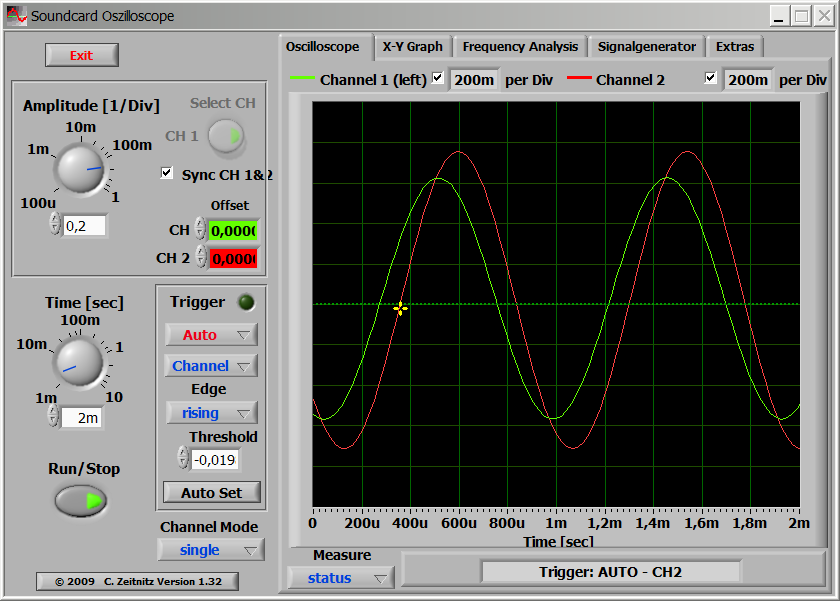
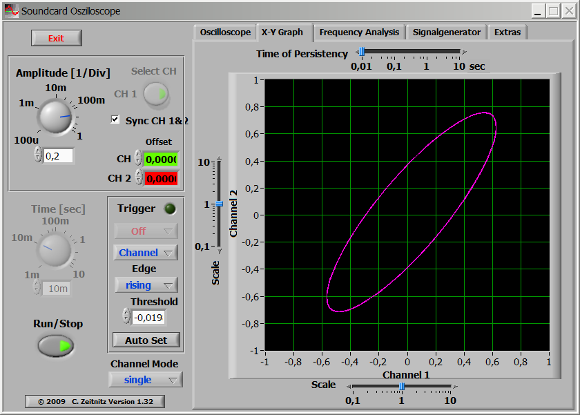
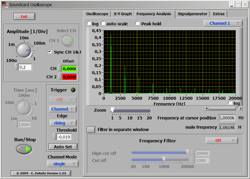
The user interface of the Soundcard Oscilloscope by Christian Zeitnitz.
(click on the image to view it in full size)
Responsible for these pages: U. Zimmermann