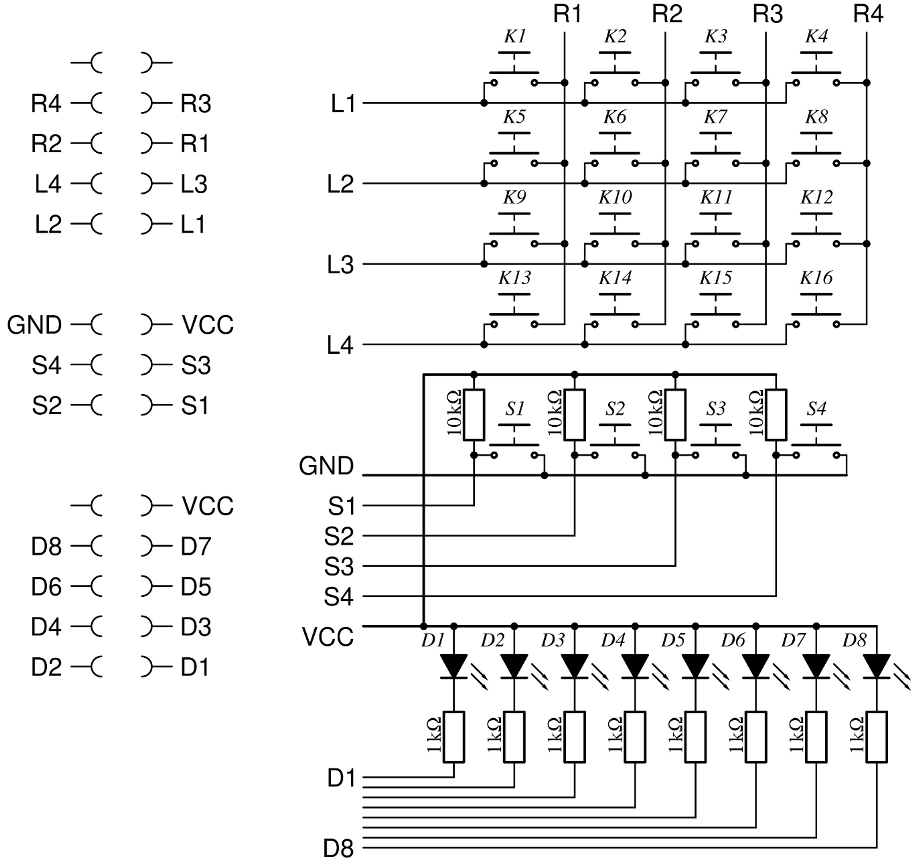
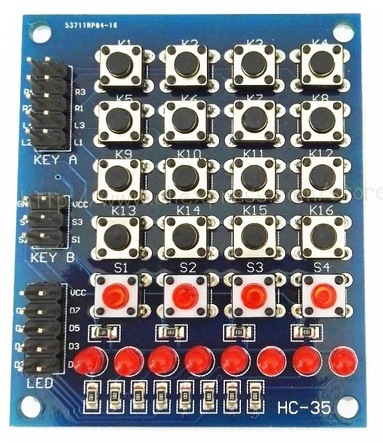
On your favorite selling sites for cheap electronics you may find a nice looking keypad/push button matrix with 16 black buttons arranged in a 4×4 matrix, another row of 4 red buttons and a row of eight 3mm red LEDs.
But how is everything connected internally to the three pinheaders on the board (5×2 pins, 3×2 pins and 5×2 pins)?
Since there was a big lack of information on all the sellers’ sites, and even a search did not bring up clear information I beeped through all the wires and here is the internal circuit diagram. It’s a mix of a multiplexed matrix, direct push buttons with applied 10 kΩ pull-up resistors and the LEDs in a common-anode (CA) configuration with 1 kΩ resistors.