
The trick is not new, it is utilized in the AVR transistor tester which you can buy for quite cheap money from China, and it has been discussed in internet forums for almost 10 years (see below for some links).
The Atmel AVR microcontrollers feature an analog to digital converter (ADC) equipped with a multichannel multiplexer. Most of these channels are mapped to GPIO pins on the package of the chip, but some channels are reserved for special purposes. In the ATmega48(P) series these are
- channel 8 (MUX3…0 = 0b1000) a temperature sensor
- channel 14 (MUX3…0 = 0b1110)
 (VBG)
(VBG) - channel 15 (MUX3…0 = 0b1111) 0 V (GND)
The ADC also allows three valid choices for its reference voltage
- 0 (REFS1…0 = 0b00) external voltage at AREF
- 1 (REFS1…0 = 0b01) AVcc
- 3 (REFS1…0 = 0b11) internal bandgap reference (VBG)
There is some dispute on the internet on the quality of the internal bandgap reference voltage of the ATmega series. It is high on my personal to-do list to actually perform some intense testing, because according to the datasheet the internal reference section of the ATmega series should be quite good, and why shouldn’t it? It’s not too difficult to integrate a high-quality bandgap reference into a chip nowadays…
For a current project at Uppsala University I was redesigning our circuit these days. The project is in principle a data logger, and it is supposed to be monitoring its battery voltage. In the previous design I employed a low-side switchable voltage divider which I also plan to describe here in the future, but in the new design where the ATmega is run directly from the battery voltage, I thought of employing the possibilities which the configurable ADC offers. Essentially the sequence is as follows:
- select the supply voltage AVcc as reference voltage
- switch the internal bandgap voltage to the ADC input
- measure the internal bandgap voltage
The result is a 10-bit value ADC representing the fraction of the (assumed) known bandgap voltage VBG in the supply voltage AVcc:
[{rm AV_{cc}} = frac{V_{BG}}{rm ADC}cdot 1023 = frac{SI{1.1}{volt}cdot 1023}{rm ADC}]
How surprised was I know when I did a quick test with an ATmega328P on a breadboard that the measured voltage AVcc was off by more than 20%! This is unreasonable given the specifications of the datasheet!!!
I consulted the internet and found a lot of opinions on the topic, many of which just plainly blaming the poor stability or quality of the internal reference voltage. And I was beginning to agree – the general ideas were:
- poor quality of the internal bandgap reference
- poor internal design of the analog multiplexer
- sensitivity of the timing
- sequence of switching the reference voltage
- sequence of switching the input multiplexer
- discard the first ADC reading because of possible glitches
I decided to do some quick testing in spite of many other things on my current agenda. The first thing was to check the internal bandgap voltage itself. You don’t have to open the chip to do so! When selecting the internal bandgap voltage as reference for the ADC, the voltage is available on the AREF pin of the ATmega328 where it should be bypassed with a  capacitor. But this also allows you to just measure the voltage with a multimeter. I measured
  on a 3-1/2 digit multimeter – completely within specifications!
The next thing to test was the back-and-forth switching of the reference voltages and of the input multiplexer. It is difficult to do this in a concise manner, but I thought out some repeating sequence. Monitoring the ADC conversion results over a UART interface it became clear that indeed the conversion would after a while settle to a stable – and good – result, however, it still appeared to be somewhat non-deterministic. I had written a C-function for the measurement of the supply voltage, but almost independent on what I did in this function, it would never give back a good result. On the other hand the inline code with UART-debugging worked flawless. So it must surely be a timing problem.
I did some more testing and here is the main result:
You have to wait at least
after switching the input multiplexer of the ADC converter to the bandgap voltage VBG before you will get a reasonable result.
In order to be sure I decided in my code to wait three times longer,  . After all you will not want to do these measurements frequently in your code.
This waiting time appears to be independent on supply voltage, switching sequence and clock-frequency. The most probable cause is that the internal bandgap voltage is fed from a very resistive source onto the multiplexer. Since the multiplexer itself connects to the sample-and-hold capacitor of the analog to digital converter, the series resistance together with the capacitance gives you a significant time delay!
This is not mentioned in the datasheet!
This slow reaction time appears to only affect the use of the bandgap voltage as the input to the analog to digital converter – switching between different reference voltages is much faster, probably because in that case no sample-and-hold capacitor is involved!
Finally, here is some working code for you:
#include <avr/io.h>
#include <util/delay.h>
#define ADMUX_ADCMASK ((1 << MUX3)|(1 << MUX2)|(1 << MUX1)|(1 << MUX0))
#define ADMUX_REFMASK ((1 << REFS1)|(1 << REFS0))
#define ADMUX_REF_AREF ((0 << REFS1)|(0 << REFS0))
#define ADMUX_REF_AVCC ((0 << REFS1)|(1 << REFS0))
#define ADMUX_REF_RESV ((1 << REFS1)|(0 << REFS0))
#define ADMUX_REF_VBG ((1 << REFS1)|(1 << REFS0))
#define ADMUX_ADC_VBG ((1 << MUX3)|(1 << MUX2)|(1 << MUX1)|(0 << MUX0))
// measure supply voltage in mV
uint16_t measure_supply(void)
{
ADMUX &= ~(ADMUX_REFMASK | ADMUX_ADCMASK);
ADMUX |= ADMUX_REF_AVCC; // select AVCC as reference
ADMUX |= ADMUX_ADC_VBG; // measure bandgap reference voltage
_delay_us(500); // a delay rather than a dummy measurement is needed to give a stable reading!
ADCSRA |= (1 << ADSC); // start conversion
while (ADCSRA & (1 << ADSC)); // wait to finish
return (1100UL*1023/ADC); // AVcc = Vbg/ADC*1023 = 1.1V*1023/ADC
}
int main(void)
{
uint16_t voltage;
// initialize the ADC
ADMUX = (1 << REFS1) | (1 << REFS0)
| (0 << ADLAR)
| (0 << MUX3) | (0 << MUX2) | (0 << MUX1) | (0 << MUX0);
ADCSRA = (1 << ADEN)
| (0 << ADSC)
| (0 << ADATE)
| (1 << ADPS2)|(0 << ADPS1)|(1 << ADPS0);
ADCSRA |= (1 << ADSC); // start dummy conversion
while (ADCSRA & (1 << ADSC)); // wait for dummy to finish
// do whatever you want....
voltage = measure_supply();
}
Continued on
ATmega328P – measuring its own supply voltage II

Pingback: ATmega328P – measuring its own supply voltage II « GreenPhotons
Pingback: ATmega328P – measuring its own supply voltage II « GreenPhotons
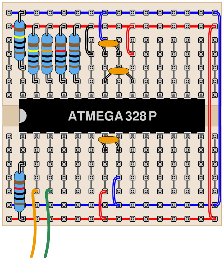
Thanks for the very clear write up and the investigation! I like your circuit diagram at the top of the page. What did you make it with?
Since about the year 2000 I have made almost all of my circuit diagrams and a couple of other drawings in XCircuit – and this one is no exception.
http://opencircuitdesign.com/xcircuit/