OctoPi - WiFi issues
Next step in my journey into 3D-printing would be to set up a server to remote-control my 3D-printer. Since two weeks ago I have a spare Raspberry Pi 2 lying…

Next step in my journey into 3D-printing would be to set up a server to remote-control my 3D-printer. Since two weeks ago I have a spare Raspberry Pi 2 lying…

Yesterday I got my Winhao Duplicator i3 and when I was setting it up and adjusting the print bed I thought: "Is it supposed to be like this?" The print…

…it arrived by mail today – and I couldn’t wait…


It's been a while since I exposed my students to counterfeit chips from dubious eBay channels, but now it has happened again. For a couple of projects I provided my…
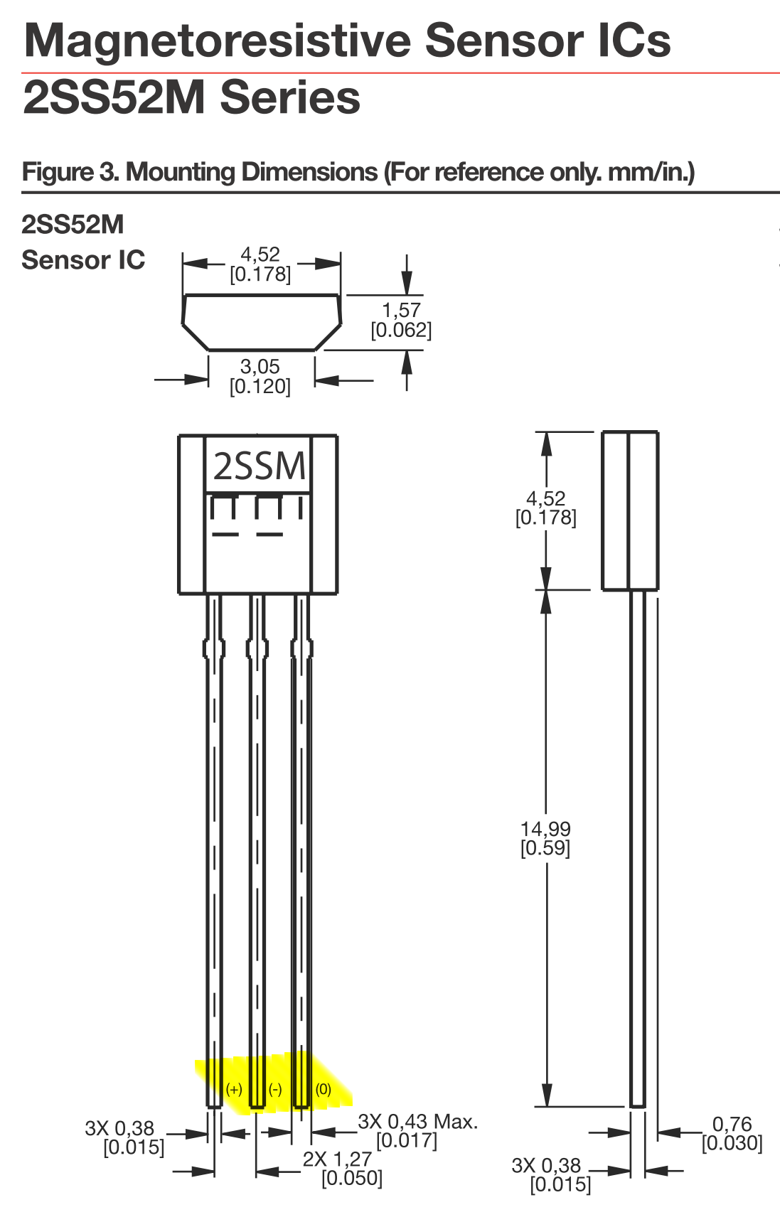
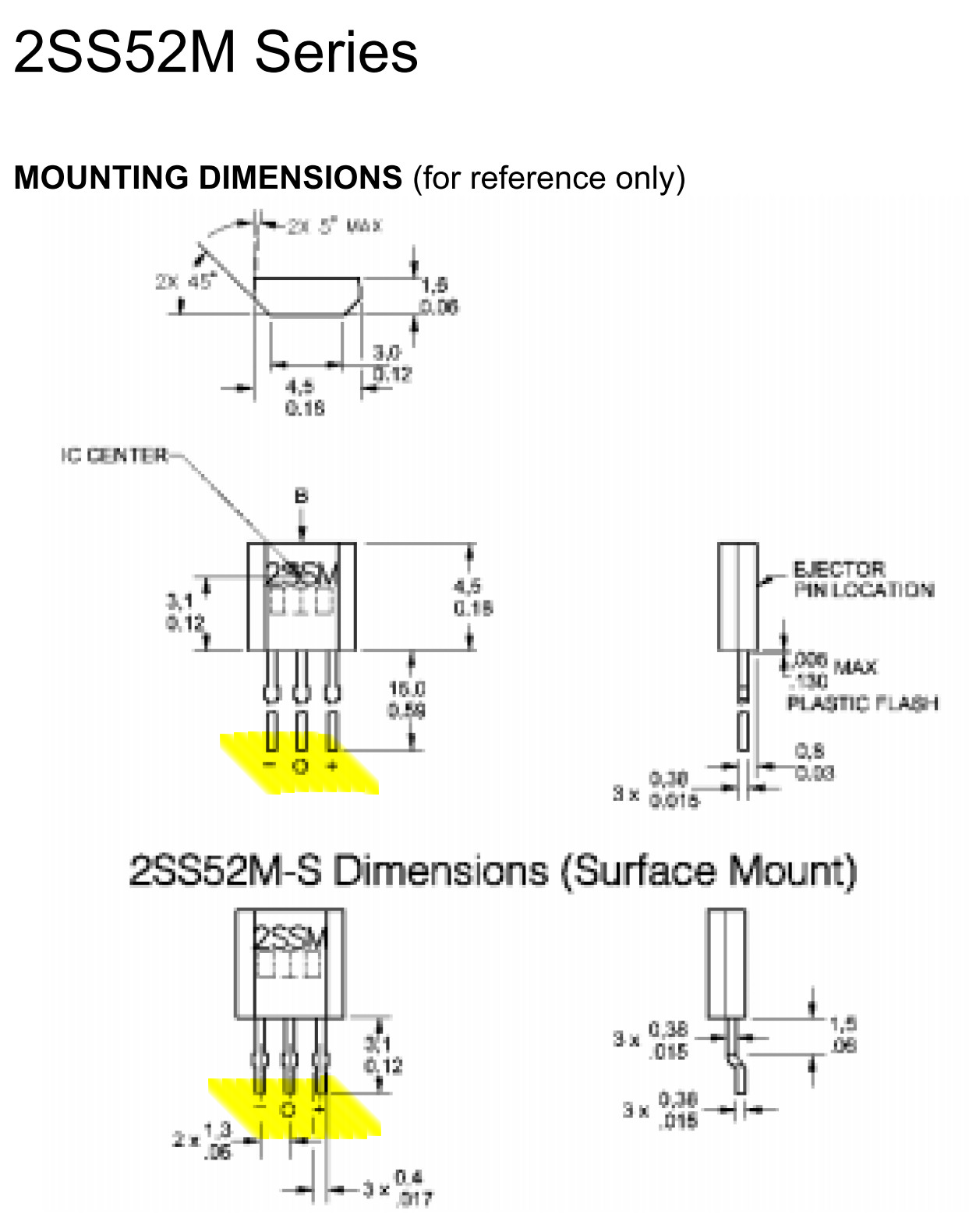
Today I wanted to use a magnetic sensor for a small project. I had three Honeywell 2SS52M sensors in my stock – a magnetoresistive switch, more sensitive than your usual Hall-effect based ones. For my project it didn’t matter, but since I had these lying around I could as well put them to some use.
Since I didn’t know the exact pinout of these TO-92-similar devices, I asked Google. The first link after the advertisements was the direct link to the datasheet on Honeywell’s homepage.
Happily I realized that it was supposed to have the same pinout as the more common Hall-effect sensors, e.g. the venerable A3144 from Allegro. When my AVR-programmer decided to switch itself off after connecting the finished circuit I got a bit suspicious, but not suspicious enough to not burn up two out of three of my sensors.
What had happened?
Well obviously there is a printing error in Honeywell’s most recent datasheet, dated March 2016. Figure 3 should show the pinout of the sensor, but if you compare it to an older (less fancy) version of the datasheet, which the internet hadn’t forgotten, then you will see the difference. I assume that Honeywell has not changed the actual pinout of the devices in production – let’s see and wait if they will answer my email pointing out their mistake.


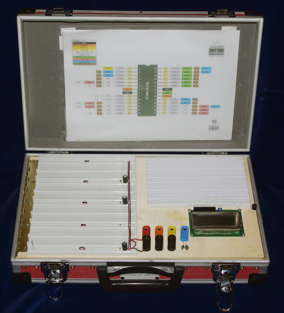
A couple of years ago I mounted an Atmel STK500, a couple of breadboards and a power supply in a briefcase. This allowed me to bring test circuits to my lectures and demonstrate them in the class room.
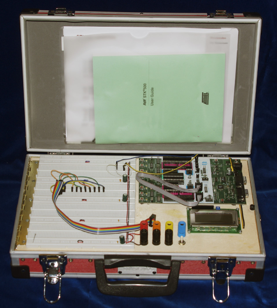
Since I now have abandoned the STK500 in favor of just a USB programmer for AVR microcontrollers, I decided to rip out the STK500 and instead mount even more breadboard tiles inside the briefcase. This is how it looks now:

I just watched some videos and got inspired... Are Your Capacitors Installed Backwards? Capacitors 1965 US Air Force Training Film

[latexpage] After the first two parts of this series ATmega328P – measuring its own supply voltage ATmega328P – measuring its own supply voltage II where I investigated the possibility of…
[latexpage] Here is a brief follow up from yesterday's post on the internal reference voltage VBG of the ATmega328P. I wrote a small test program where I wait for a…