Today I was at Bauhaus in Uppsala, just browsing, not looking for anything special. Close to the exit there was a table with LED light bulbs which were obviously taken out of the regular assortment and re-labelled with new prices.
Usually you would expect a bargain – and since I am somewhat sold to LED light bulbs I had a close look.
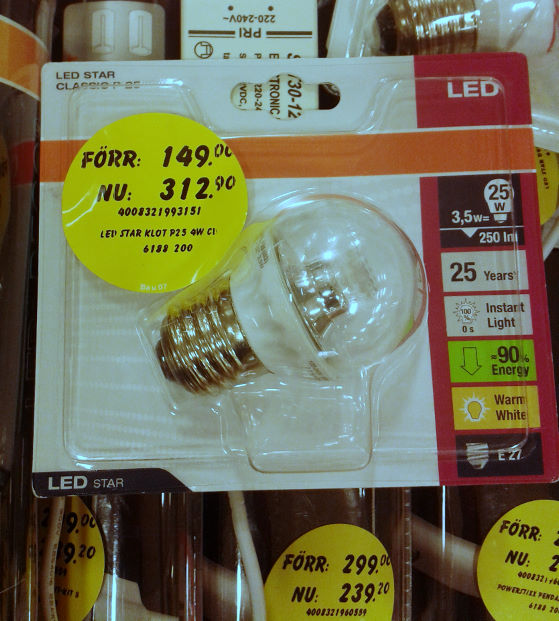
Well it was not worth the looking – these were still quite overpriced as compared to the average shop price, not to mention the internet price. but then I saw one very special offer:
Special offer on LEDs at Bauhaus: new price twice as high as before!
It's almost 4 years now since I installed my server and I decided it was time for some new (bigger) harddisks. I wrote about my server earlier in my blog,…
The Swedish education system used to be a good example, but looking at the new PISA results, Sweden is among the countries with the strongest deterioration in school education in reading, mathematics and science. The only thing Sweden has achieved is to narrow the gap between top and low performers – obviously by lowering the overall average.
It is also notable that in spite of worse performance the belief of the students in their abilities is increasing in Sweden.
I cannot say that I am completely surprised by these findings…
(Internal server error? – Try again in a second, the PISA server appears to be heavily loaded right now.)
[latexpage] I am planning to construct a logarithmic current meter and were yesterday doing some simulations with LTspice. Using a logarithmic converter you can span a wide range of currents…
Yesterday I had the opportunity to watch a screening of the movie Pandora's Promise at Uppsala University. After the movie there was a panel debate including the director of the…
I recently got hold of another broken Samsung monitor. This time it is a Syncmaster 913TM which is characterized by its swiveling stand, which allows the screen to be rotated…
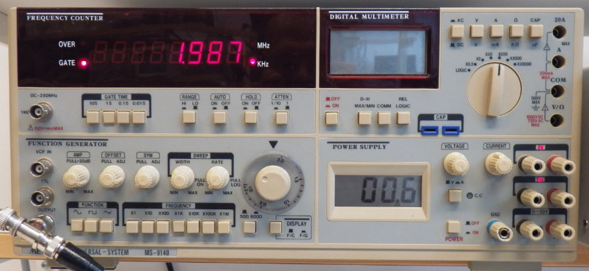
Every place in our course laboratory is equipped with an analog oscillsocpe and a Metex Universal System. This instrument consists of a power supply with two fixed and a variable outpur voltage, a multimeter, a function generator and a frequency counter. This sounds nice and it usually is – most of the time the instrument works satisfyingly for our experiments, but there are some disadvantages and most of all it’s not student proof.
Metex MS-9140 Universal System.
First there are several models with somewhat different features – mostly it is the frequency counter and the multimeter which differe between models. The apparently newest series is equipped with green LED displays which are impossible to read, because the company Metex was cheap on a green filter in front of the display. We solved this issue in our lab with pieces of green plastic foil – at a cost of practically nothing, but it makes you wonder if any engineer from Metex has ever been trying to sit in front of the instrument.
Then there is the multimeter. The whole instrument is connected to the power line and its functions powered from internal power supplies – everything but the multimeter. That one is powered by a 9V-battery which is located inaccessibly on the back of the instrument. I thought I knew the reason and assumed the multimeter was based in the standard voltmeter circuit ICL7106 which has the disadvantage that it cannot measure with reference to its own ground potential. The simple way would then have been to just move the whole circuitry from a handheld multimeter (and Metex has become a big company just by making these kinds of multimeters) into the big box, including the battery. The other possibility would have been to use a dc/dc converter which would have added a cost of a few dollars.
As I wrote, I thought I knew. But no… According to the Service Manual the internal multimeter is based on a MAX134 which is well capable of measuring with reference to its own ground potential, and as another matter of fact the display of the built-in power supply is based on the ICL7106 which is powered from a separate winding of the transformer. So WHY?
Finally to today’s problem which triggered this post. One student group ran into problems when they connected their function generator to their self-built transistor amplifier. Just when they connected the function generator the sine curve on the oscilloscope showing the output of the function generator flatlined: But they were sure that their amplifier circuit was ok -after all, that’s what they built themselves… With 20 other groups in the lab at the same time they took the function generator (a 20kg box) from the unoccupied neighboring place and connected it up – and it showed the same misbehavior – what a stupid course lab with all this broken equipment. Before they got to the third function generator I came by – they told me of their problems with the broken equipment, but I became suspicious that there should be such an assembly of broken equipment in just this corner of the lab. I checked their circuit, which connected the +15V supply of the transistor directly to its input and from there of course into the output of the function generator. The broken ones actually smelled slightly badly from their ventilation openings…
If Metex had included a fuse in the output of the function generator it could have been student proof – now I wonder if we can add this feature by ourselves and upgrade these instruments.
A good question was brought up by my students in the lab exercise in the course Electronics I yesterday: What actually makes the cut-off frequency of a filter circuit (1st order) so special? Why do we look out for a point which happens to be located or a factor of under the amplitude of the pass band? Why not , , ?
The first answer, which has some historical relevance, would be to look at a resistor and a signal with an amplitude and another signal with an amplitude while calculating the electrical power:
[ P_0 = frac{V_0^2}{R}qquad P_1 = frac{V_1^2}{R} = frac{left(V_0,sfrac{1}{sqrt{2}}right)^2}{R} = frac{1}{2},P_0 ]
The power has been reduced to half the original power, it could be the electric power which is converted to sound waves in a speaker, or the power converted to electromagnetic waves in an antenna.
But already here we can make one important observation:
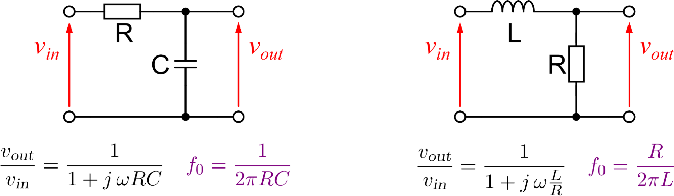
Is this everything then? It still sounds random to choose exactly this point. If we for example look at a simple RC filter then we can show another reason which makes this point’s frequency so special. In a low-pass filter we have a constant amplitude for low frequencies while we observed mathematically and experimentally that the amplitude drops with per decade of frequency for high frequencies. If we draw out these two asymptotic lines in a Bode diagram, then we will find exactly one point where the lines intersect – you guessed it: it’s at the cut-off frequency (the same holds of course true for a high-pass filter). We can see this if we zoom into the area around the cut-off frequency in a Bode diagram: Bodediagram of a low-pass filter – zoomed into the area around the cut-off frequency.
Then was this everything now? Is there more about the cut-off frequency?
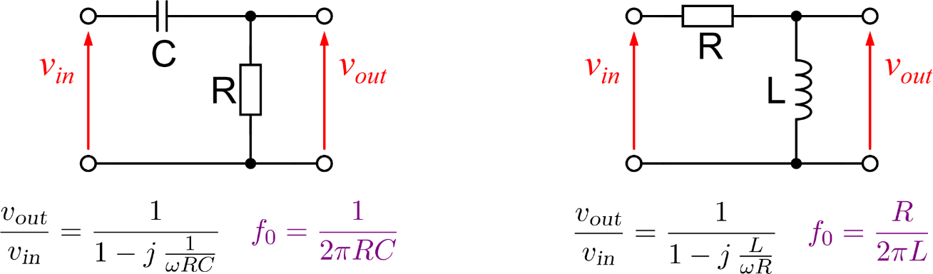
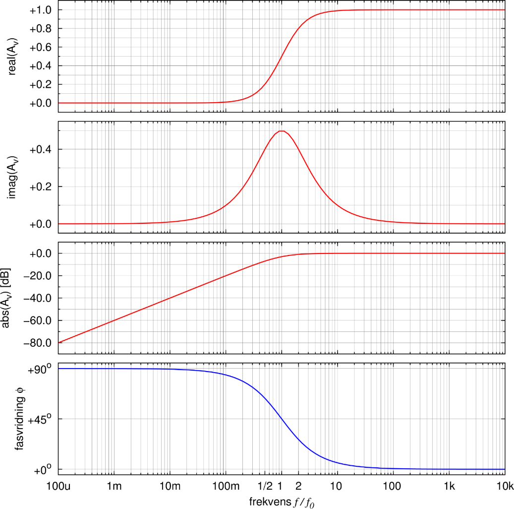
As we also saw we have a phase angle of (high-pass) or (low-pass) between the input- and the output signal at the cut-off frequency. In the complex notation of the -method this correlates to the fact that the real and the imaginary part of the transfer function have the same magnitude at this point. The relation between real part, imaginary part, amplitude and phase angle I have plotted below for both the low-pass and the high-pass filter.
It is interesting to observe that the imaginary part actually reaches a minimum at this point ( for the low-pass filter) or a maximum ( for the high-pass filter), respectively.
You can see that the cut-off frequency actually is a remarkable point for a filter circuit.
We use cookies to ensure that we give you the best experience on our website. If you continue to use this site we will assume that you are happy with it.OkNoPrivacy policy


 or a factor of
  under the amplitude of the pass band? Why not
  ,
,  ,
,  ?
? and a signal with an amplitude
  and another signal with an amplitude
  while calculating the electrical power:
![20log_{10}left(sfrac{1}{sqrt{2}}right)=SI[output-decimal-marker={.}]{-3.0103}{dB}approxSI{-3}{dB}](https://www.sciencetronics.com/greenphotons/wp-content/ql-cache/quicklatex.com-44d2232d1795c1343fe5de3dd8944da4_l3.png "Rendered by QuickLaTeX.com")
 for low frequencies while we observed mathematically and experimentally that the amplitude drops with
  per decade of frequency for high frequencies. If we draw out these two asymptotic lines in a Bode diagram, then we will find exactly one point where the lines intersect – you guessed it: it’s at the cut-off frequency (the same holds of course true for a high-pass filter). We can see this if we zoom into the area around the cut-off frequency in a Bode diagram:
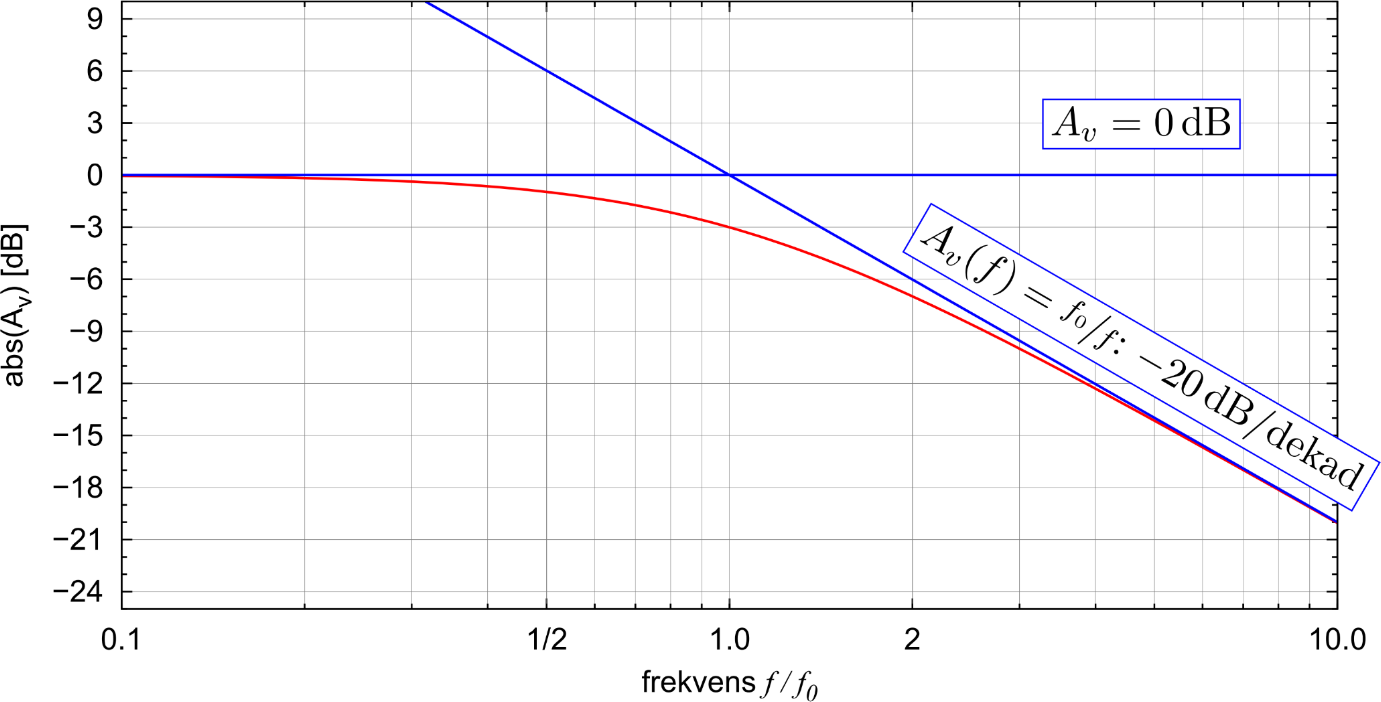
 (high-pass) or
  (low-pass) between the input- and the output signal at the cut-off frequency. In the complex notation of the
  -method this correlates to the fact that the real and the imaginary part of the transfer function
  have the same magnitude at this point. The relation between real part, imaginary part, amplitude and phase angle I have plotted below for both the low-pass and the high-pass filter.
 for the low-pass filter) or a maximum (
 for the high-pass filter), respectively.