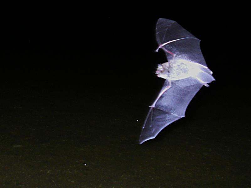
Daubenton's Bat over lake Trehörningen, Fjällnora, Uppsala, Sweden.
Recently I was on a field trip with some friends where I shot my
photo of the year - just free-hand and into the dark. Even before I
have been amazed by bats since I saw the first one on a summer vacation
in Sweden with my
parents in the 1980's.
So now I searched the web for schematics for a bat detector which
converts the bats' ultrasonic sonar signals into audible sounds - a
concept which reminds me of my past listening to military
radar signals in the navy, 20 years ago...
1. Introduction
2. Function
3. Operating
Bats use ultrasonic signals for echolocation in order to find their way
and their prey in the dark. I was especially impressed
by seeing a group of about 4 bats of the species Daubenton's Bat, Myotis
daubentonii,
in a recreational area close to Uppsala/Sweden. The German and Swedisch
name of this bat translates to "water bat" and
describes these little critters much better than the English term.
These bats can fly just a few inches above the water surface - in pitch
black!
According to different sources the ultrasonic signals of bats range
from about 10 kHz to about 200 kHz (see e.g. S. Parsons and G. Jones: The Journal of
Experimental Biology 203, 2641–2656 (2000).
And there are four major techniques to transpose the ultrasonic signals
into human-audible sounds:
Bertrik's bat detector page is a
nice starting point on the web when looking for more details
and other ideas.
The heterodyne mixer principle seemed to me the most promising design
for my
own bat detector. However, most of the circuits on the net require some
special parts, like dedicated mixer circuits (TCA440, NE602, or alike),
which I didn't have in my bag of parts at home...
So I ended up taking the best ideas of the designs on the web and
make my own construction around these with the parts I had at hand.
2008-10-16: Thanks Owen Tanner for pointing out some errors on this page and in the schematics diagram. Firstly, I had swapped two pin numbers on the flip-flop U2 in the diagram, then I was obviously not able to count all the small capacitors correctly....
2.1 overview
2.2 microphone preamplifier
2.3 voltage-controlled oscillator
2.4 switching mixer
2.5 audio amplifier
2.6 complete parts list
The following figure shows the complete schematics of the bat detector. No, you are not supposed to see this image clearly, nor to completely grab
the function from this figure. A high-resolution PDF file can be downloaded by just clicking on the image or its caption. And below follows a more
detailed description of the individual sections of this design.
Just to give a brief overview over the bat detectors specifications: the audio path is layed out in stereo in order to use two
microphones and give a directional sensitivity to the detected bat signals. The heart of the detector is a switched mixer
which is controlled by a two-phase digital clock generated from a voltage controlled oscillator. Since the shaping of
the two-phase clock is done by synchronous division, the VCO runs at twice the tuning frequency.
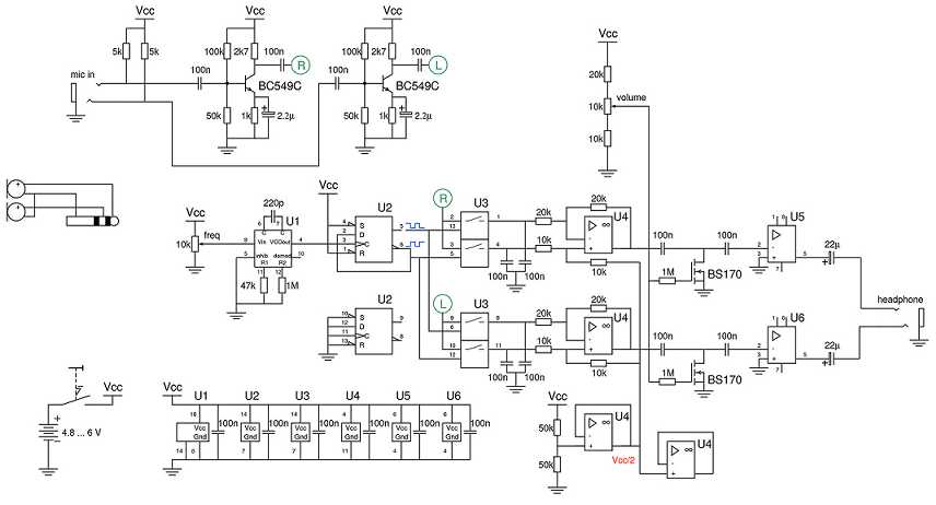
Schematic of the full circuit of the
bat detector.
(click on the image to download PDF)
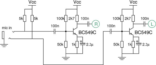
The microphone preamplifier.
Nothing special here. The signal from the electret microphones is amplified in a standard emitter-follower, using a standard NPN silicon transistor. The amplifier is designed to give a voltage amplification of the input signal of about 50x or 17dBv.
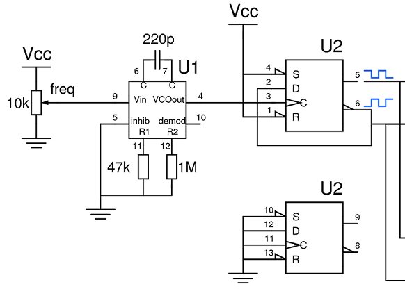
The voltage-controlled oscillator.
The 74HC4046 contains all functional parts for a phase-locked loop. In the bat detector I only use the linear VCO
in order to generate the digital clock for the switched mixer. Following the manufacturer's datasheet the two resistors
on pins 11 and 12 narrow the frequency range of the VCO between a lower and upper frequency, which in turn depend on the
frequency-determining capacitor between pins 6 and 7. I determined the values in the design experimentally in a
bread board design in order to match the frequency range I wanted to cover.
It is of course possible to use the 4046 from the older standard CMOS series, since there are
no critical demands on either the power supply voltage or frequency limit of the device in this circuit.
In this case a standard CMOS flipflop and the standard CMOS version of the analog switch in the mixer should be used.
As mentionned above the bats' frequency range stretches from 10 kHz to about 200 kHz. With the component values given and
a supply voltage between 4.8V (four NiMH cells) to 6V (four alkaline cells), the VCO can be tuned between
about 20 kHz and about 400 kHz.
In the following stage the VCO output signal is divided by 2 in one half of the 74HC74 flipflop. The output of the flipflop generates
two - essentially not overlapping - clock signals which will drive the mixer.
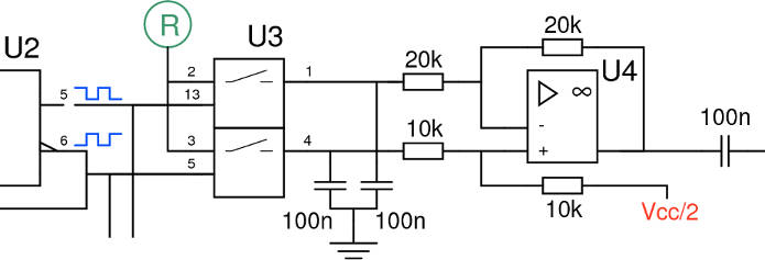
The switching mixer.
In order to transpose the bat ultrasonics into audible sounds the amplified signal from the microphone is mixed with the VCO frequency. This results in the sum and difference frequencies to be generated between the two signals. I chose to use a switching or commutating mixer, mostly because of two reasons:
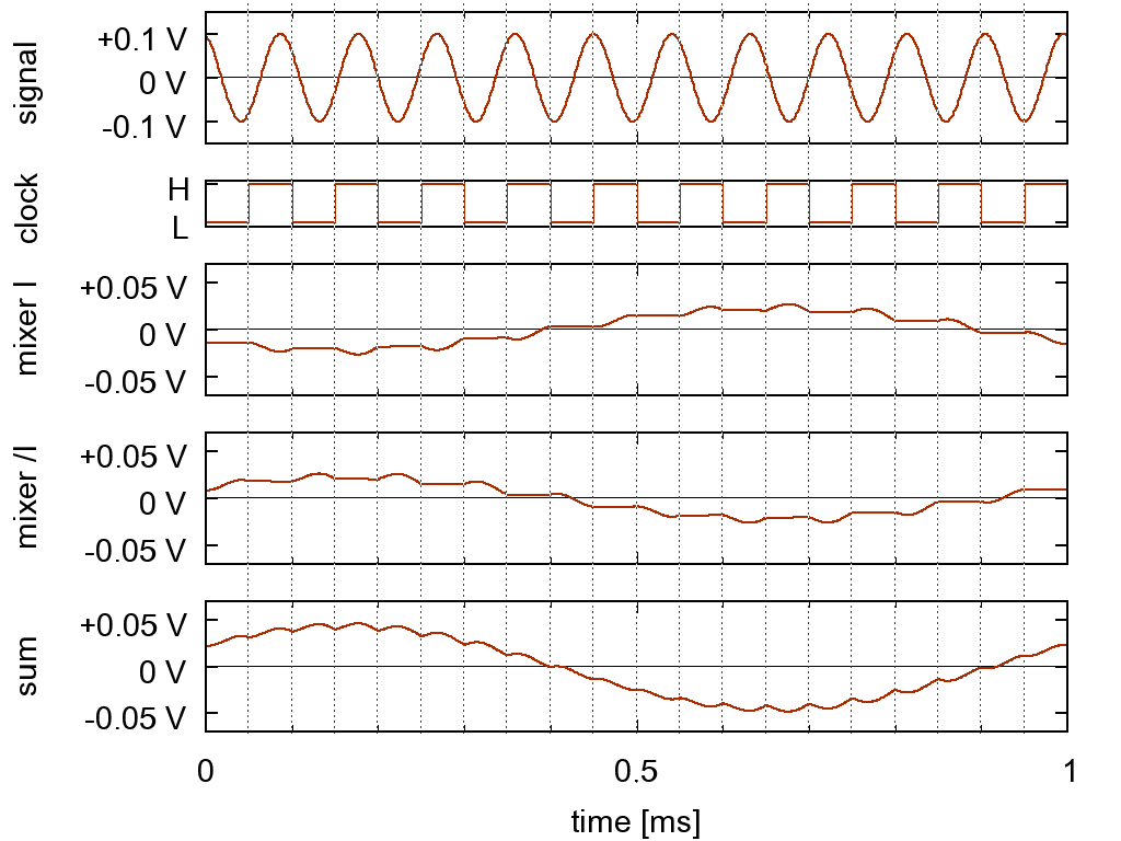
The switching mixer. PSpice simulations of an input signal at 11 kHz and a clock signal at 10 kHz.
The resulting signal after the mixer has a frequency of 11 kHz - 10 kHz = 1 kHz.
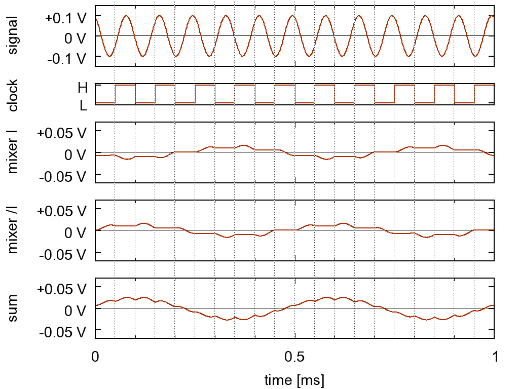
The switching mixer. PSpice simulations of an input signal at 12 kHz and a clock signal at 10 kHz.
The resulting signal after the mixer has a frequency of 12 kHz - 10 kHz = 2 kHz.
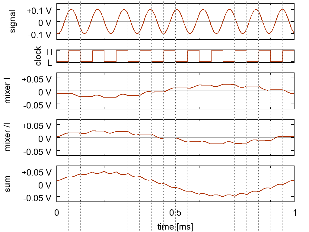
The switching mixer. PSpice simulations of an input signal at 9 kHz and a clock signal at 10 kHz.
The resulting signal after the mixer has a frequency of 10 kHz - 9 kHz = 1 kHz.
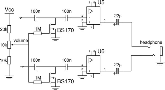
The audio amplifier.
There is not much special about the audio amplifier section. In order to implement a stereo volume control with a mono
potentiometer I had to come up with a voltage controlled amplifier. This is done with the two MOSFET transistors of type
BS170. This is not a hifi circuit, but it doesn't need to be - this is a bat detector, remember?
The values for this part of the circuit have been determined at the actual devices I used in my own prototype. This means that you
might need to vary some of the values depending on the characteristics of your MOSFETs. You should also preselect a
pair of MOSFETs with similar characteristics, or you might end up with an unsymmetric volume control.
In my prototype I adjust the gate voltage of both MOSFETs between 1.25 V for maximum and 2.5 V for minimum
volume. At the higher gate voltage the MOSFET channel becomes conductive and shorts out part of the audio signal to ground,
reducing the audio signal amplitude.
Finally the audio signal is amplified by a LM386 audio amplifier (U5 and U6) in its most simple application circuit. And then you
can connect an ordinary pair of headphones and listen to those little vampires.
| Partlist | |||
|---|---|---|---|
| count | value | type | comment |
| Capacitors | |||
| 6 | 100nF | ceramic | supply decoupling |
| 12 | 100nF | MKT (or ceramic) | audio coupling |
| 2 | 2.2µF | electrolytic | bypass |
| 2 | 22µF | electrolytic | audio coupling |
| Resistors | |||
| 2 | 1kΩ | ±5% | |
| 2 | 2.7kΩ | ±5% | |
| 2 | 5kΩ | ±5% | |
| 5 | 10kΩ | ±5% | |
| 5 | 20kΩ | ±5% | |
| 5 | 47kΩ 50kΩ |
±5% | I used 50kΩ because I have plenty... |
| 2 | 100kΩ | ±5% | |
| 2 | 1MΩ | ±5% | |
| Variable resistors | |||
| 2 | 10kΩ | linear | |
| Transistors | |||
| 2 | BC549C | NPN | mic preamp |
| 2 | BS170 | MOSFET | volume control |
| Integrated circuits | |||
| 1 | 74HC4046 | VCO | |
| 1 | 74HC74 | dual FF | |
| 1 | 74HC4066 | quad analog switch | |
| 1 | LM324 | quad opamp | single supply |
| 2 | LM386 | audio amplifier | |
| other stuff | |||
| 2 | microphones | electret with FET | |
| 1 | switch | spst | on-off |
| 2 | stereo jack | 3.5mm TRS | |
| 1 | stereo plug | 3.5mm TRS | |
| 1 | battery holder | 4x AA or AAA | |
| 1 | box | ||
| 1 | stereo headphone | ||
I have tested the prototype with my analog oscilloscope and a signal generator connected to a small piezo speaker as signal source for the bat detector. The tuning range is from about 15 kHz to around 180 kHz. The output signal for the headphones for a sinusodial input signal was surprisingly sinusodial - given all the non-ideal audio signal processing involved, even though I have no means to determine the total harmonic distortion of the signal.
I will fill this section as soon as I have captured some bat calls. On saturday night, 2008-08-16, I picked up my very first bat sound with the prototype device. So, yes, it is working!
Responsible for these pages: U. Zimmermann