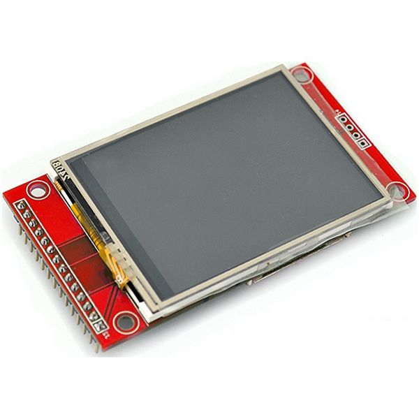
It’s been a while since I purchased some TFT modules on eBay. These modules come in different sizes and two varieties – with and without integrated touch controller XPT2046. The controller in the TFT display itself is an ILI9341 wired up to be controlled by SPI.
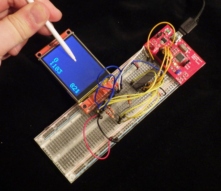
When planning my new remote control project I briefly considered using one of these displays as the main control unit featuring soft-buttons for the different buttons on my remote control unit. However, I then decided that even the biggest 2.8 inch display which I had would not allow to conveniently place 32 buttons without the necessity to use a stylus. So the breadboard with the attached ATmega328P, programmer and display was put to the side before I even started programming.
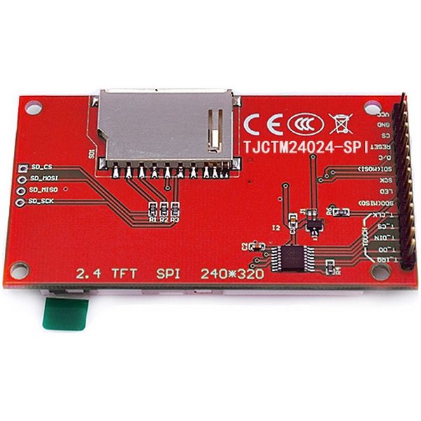
These modules feature a separate slot for an SD-card with its own connector which I will ignore for this post.
The rest of the module is connected to a 14×1-pin pinheader:
| 1 | Vcc | 8 | LED |
| 2 | Gnd | 9 | TFT DO |
| 3 | TFT CS | 10 | Touch SCK |
| 4 | TFT RESET | 11 | Touch CS |
| 5 | TFT DC | 12 | Touch DI |
| 6 | TFT DI | 13 | Touch DO |
| 7 | TFT SCK | 14 | Touch IRQ |
So, both chips on this module use SPI and since both have separate chip select pins (CS) implementing full 4-wire SPI interfaces it should be possible to connect both of them to the hardware SPI interface of an Atmel ATmega328P – this way the display module including touch would only use 7 pins in total – that’s as many pins as you usually need for an HD44780-compatible text based LCD!
Why 7 pins? There are the three basic SPI pins (SCK, MOSI, MISO), the two CS pins and an additional two pins (RST and DC) for the display. And indeed there was one site on the internet showing this connection: Nailbuster Software Inc. shows on their blog how to connect such a module in this configuration to an ESP8266 wifi module.
As usual most implementations and libraries out there use the Arduino framework which I despise, so I knew that I had to do some programming on my own. However, the handling of the touch controller didn’t seem too complicated, even though the datasheet of the XPT3046 is only a very poor copy of the datasheet of the Burr Brown/Texas Instruments AD7843 – I mean, if you do nothing than to copy a datasheet, how can you introduce so many errors?
So I set off to connect everything together, grabbed a modified library for the graphics controller shich I had used in a different project with a display without touch, connected everything, compiled a test code and uploaded it to the ATmega328P. And while the display cooperated with me directly, I could not get any meaningful data back from the touch controller.
To clarify things, I had been using a 2.4 inch display with no particular labeling on either front or back.
I connected my 8-bit logic analyzer to the circuit in order to see the signals on the SPI bus, and it appeared that the XPT2046 touch controller was not at all responding to the correct signals it received from the microcontroller.
Could there be something wrong with the timing of the code for the XPT2046 which I had translated back from Arduino-style C++ into ordinary C? I connected the touch controller to 4 GPIO pins on PORTD of the ATmega328P and wrote a quick implementation of the SPI interface, bitbanging the GPIO pins:
#define XPT2046_CS_DDR DDRC
#define XPT2046_CS_PIN PINC
#define XPT2046_CS PC3
#define XPT2046_CS_HI() XPT2046_CS_PORT |= (1 << XPT2046_CS)
#define XPT2046_CS_LO() XPT2046_CS_PORT &= ~(1 << XPT2046_CS)
#define XPT2046_CLK_PORT PORTD
#define XPT2046_CLK_DDR DDRD
#define XPT2046_CLK_PIN PIND
#define XPT2046_CLK PD7
#define XPT2046_CLK_HI() XPT2046_CLK_PORT |= (1 << XPT2046_CLK)
#define XPT2046_CLK_LO() XPT2046_CLK_PORT &= ~(1 << XPT2046_CLK)
#define XPT2046_DI_PORT PORTD
#define XPT2046_DI_DDR DDRD
#define XPT2046_DI_PIN PIND
#define XPT2046_DI PD6
#define XPT2046_DI_HI() XPT2046_DI_PORT |= (1 << XPT2046_DI)
#define XPT2046_DI_LO() XPT2046_DI_PORT &= ~(1 << XPT2046_DI)
#define XPT2046_DO_PORT PORTD
#define XPT2046_DO_DDR DDRD
#define XPT2046_DO_PIN PIND
#define XPT2046_DO PD5
#define XPT2046_DO_STATE() ((XPT2046_DO_PIN & (1 << XPT2046_DO)) >> XPT2046_DO)
//.......
XPT2046_CS_HI();
XPT2046_CLK_LO();
XPT2046_DI_LO();
XPT2046_CS_LO(); // start xfer
for (i=0; i<8; i++)
{
if (cmd & 128) // check MSB
{
XPT2046_DI_HI();
}
else
{
XPT2046_DI_LO();
}
cmd <<= 1;
XPT2046_CLK_HI();
XPT2046_CLK_LO();
}
// we don't have access to /BUSY
// is the data valid on the falling clock edge? unclear from the datasheet, but probable
for (i=0; i < 16; i++)
{
XPT2046_CLK_HI();
dummy <<= 1;
dummy |= XPT2046_DO_STATE();
XPT2046_CLK_LO();
}
XPT2046_CS_HI();
And see there, the touch controller answered with reasonable responses – both on the hardware side, as monitored on the logic analyzer, as well on the software side from the C-code. So where was the cause of the problem?
It took me some more testing, before I found the reason for the non-responses I got on the hardware SPI-bus: it was the ILI9341 graphics controller on these particular modules – I tested two modules. The chip did not release the MISO-line of the SPI bus when not being selected by means of its chip-select input! The ILI9341 (or the display-part of the circuit board) keeps the DO-pin of the module at a solid “1” whether the CS-pin is “0” (selected) or “1” (released), however, the display itself obeys the chip select signal and does not listen to data sent while its CS is “1”.
So what can I do now in order to use these display modules with a minimum number of connections? Well the graphics routins which I use with this display do not require any read-back from the display, so the solution is easy: just do not connect the faulty DO-pin of the TFT to the SPI bus… Now the module works completely on the hardware SPI of the ATmega328P using the attached library files (work in progress).

