Most of the time I design and debug my AVR projects on solderless breadboards nowadays. And for that I have been using some different types of programmers by now: starting with the good old STK500, to different versions of USBasp clones from Chinese sellers on eBay.
In order to connect the programmers to the breadboard I started with loose wires, discovered a nice breadboard adapter from Sparkfun (now retired), before I rolled out my own version which I also use with my students.
Why another design for an AVR programmer?
Starting last year it became necessary to run some projects from batteries or at 3.3 V which is not supported by all Chinese programmer clones, and also the wiring of the supply from the programming adapter to the power lines of the breadboard added to the number of wires – and sometimes it added clutter to the breadboard.
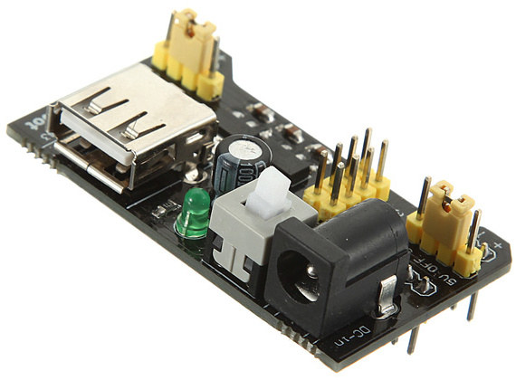
Having nothing else to do (?) I decided last weekend to design my own circuit board for the USBasp, which attaches to the breadboard much like the MB102 power supply adapter available form your favorite Chinese reseller, directly connecting to the power rails and also including a 3.3 V regulator.
Design process
I started with some compromises:
Single or double?
As usual I wanted to be able to make the circuit board using the toner transfer process and therefore it should preferably be a single sided circuit board. But this is difficult with the pinheaders which need to be on the underside, attaching to the breadboard. While it is possible to solder them this way onto a circuit board it’s usually not a good joint. I decided to start with a design for a single-sided board.
SMD or through-hole?
Most of the time I still favor through-hole design for my own projects, probably because of my big stock of through-hole parts. But I also have to acknowledge that not having to drill your own PCBs is a big advantage. When it comes to the pinheaders again, while there are SMD-versions around, I don’t trust the long-term reliability of the corresponding joints, so these would be through-hole anyway. Like the Chinese manufacturers I also went for a through-hole quartz crystal, while the rest of the board became SMD.
This way the parts and traces would be on the top of the board and the pinheaders would be soldered from the correct side.
Which USB contact?
The Chinese USBasp clones normally come with an USB-A contact, allowing them to be used like USB sticks. However, most of the time you might want to have your circuit at a flexible position and distance from your computer, making it necessary to use a USB A-A M/F extension cable. From the definition of the USB standard it would make more sense to use a B-type contact.
Just recently Dave Jones was wondering why someone would still use a mini-B type contact on their gear, not the more modern micro-B. So what should I use:
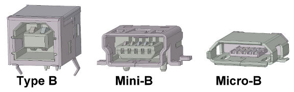
- The full size type-B connector eliminated itself, because I have the feeling that the connector and cable will put too much mechanical load onto the connection to the breadboard.
- As on most non-Apple mobile phones I have the micro-B connector on my Samsung smartphone and I don’t put too much trust into the mechanical strength of the connector.
- It remains the mini-B connector. It is a bit stronger than the micro-B, cables are still around for this connector and finally there is little use for the cables for other gadgets, helping to keep them in place…
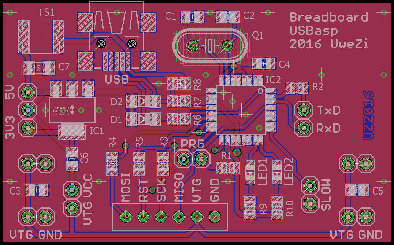
First layout
I still had plans to etch the circuit board myself, when I finished the layout. Since the circuit is quite simple it was no problem to route all traces on the top (component) side of the board. For a single-sided circuit board this would then put some challenge on the mounting of the programming connector and the three jumpers: supply voltage 5 V / 3.3 V, self-programming, and fast/slow.
For the programming connector I chose between the standard 5×2 connector from the STK500, which is also used on the Chinese USBasp clones, the more compact 3×2 connector from Atmel, also used on the STK500, or any other possible layout. For usability reasons I decided for a single row 6×1 connector and kept the pinout compatible with the Sparkfun adapter and my own breadboard adapter.
PCB production
For my private use I have only once used a professional PCB manufacturer. The Bulgarian company Bilex was recommended in a froum on the internet. Being located in Europe the turn-around time is quite fast, and shipping should be cheaper from Asia.
When designing the circuit board layout I also browsed the web for reviews of PCB manufacturers. Several lists recommended some Chinese manufacturers and I became curious. I finished the design and early Sunday I submitted the design to PCBgogo. At PCBgogo you can instantly follow the progress of your circuit board online – and I was really impressed by the speed at which things went ahead. On Tuesday the boards were ready and shipped. On Thursday I could fetch it from a DHL box in Uppsala.
I ordered the boards as follows:
- 1.6 mm FR4
- double sided
- 1oz copper
- 6/6 track and spacing
- 0.3 mm minimum drill size
- red soldermask
- white silkscreen
- HASL lead free
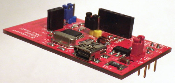
And what did I get? Exactly what I ordered!
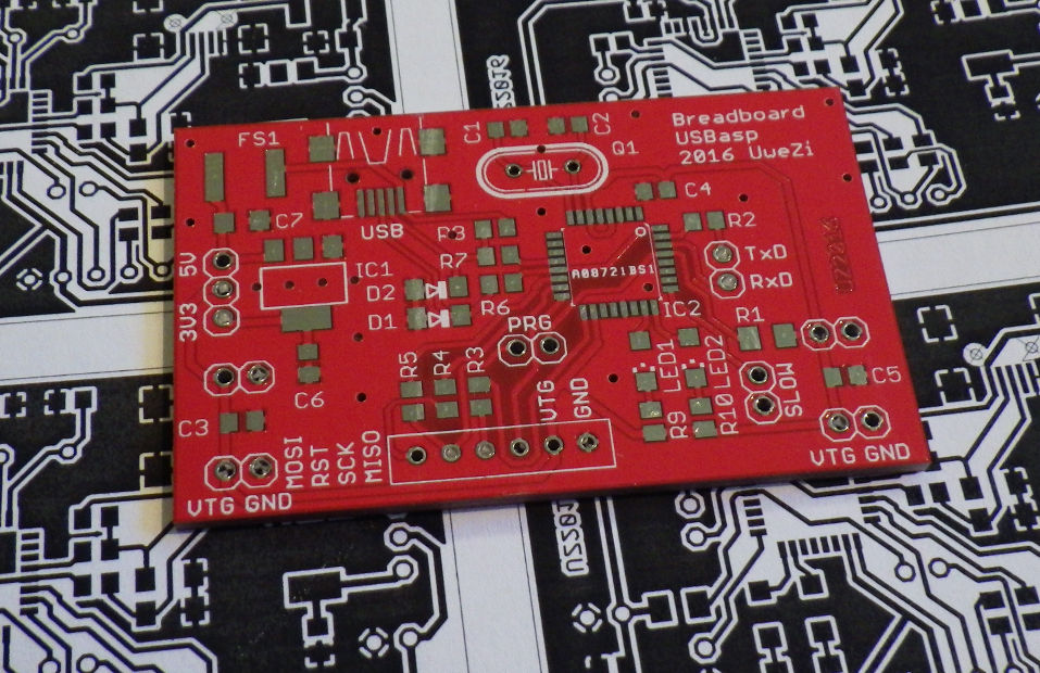
There is absolutely nothing which I could criticize with these boards, they are almost perfect. The silkscreen does move around a bit from board to board by perhaps ±0.5 mm, but that’s about it.
Soldering
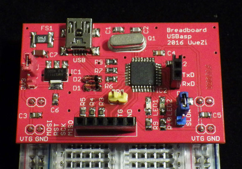
Once I had the circuit boards I could not wait to populate the first circuit board. I had almost all parts I needed – can you spot the five points where I cheated?

Testing
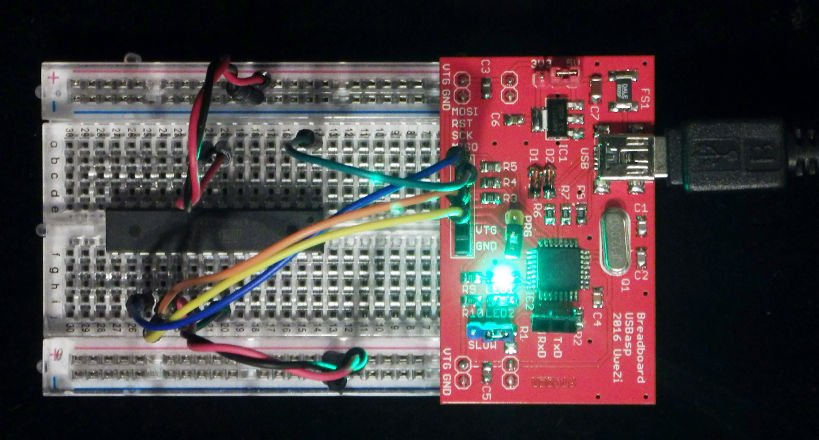
The first test was to get the firmware into the ATmega8 on the board. For this you set the PRG jumper to the closed position and attach another USBasp to the programming connector on the board. Since the layout is identical to the breadboard connectors which I normally use I could just plug it into the female header on the board. AVRDUDESS immediately recognized the ATmega on the baord, setting the fuses to run from the 12 MHz quartz crystal gave no problems either. I uploaded the latest firmware (usbasp.2011-05-28.tar.gz) from Thomas Fischl’s homepage and it works without any problem.
Improvements
I have made slight changes to the layout into what I now call version 3: there are actually three traces on the bottom side now, simplifying the layout on the top. This modification makes it less suitable for a toner-transfer DIY circuit board, but given the issues with the soldering of the pinheaders I would not recommend this method here anyway.
The original USBasp design uses 270 ohm resistors for the IO current limitation and as resistors for the LEDs. I actually used 300 ohm instead, and still the green LED is much too bright – the commercial clones from China usually use 1 kohm resistors.
Version 2 also contained a 1206 footprint for the LEDs which I changed to 0805 for version 3.
Version 3 has a better layout for the silkscreen pattern describing the pinout of the programming header.
What could further be improved would be a series jumper link to allow for an amperemeter to be inserted into the power lines for the breadboard, bypassing the programmer itself. The current routing does not allow for this feature, but with the double-sided layout it would be easy to split the supply rail.
Also it would be possible to leave the ATmega8 on the programmer to continue to run at 5 V (or 3.3 V) and implement level shifting towards the breadbord circuit. Atmel themselves used this on the STK500 with quite a simple two-transistor circuit.
Downloads
The schematics for version 2 and version 3: 20160520_AVRISP_miniusb_UZ_03dbl_SCH.pdf
Version 2 as an A5 pdf document for the toner-transfer process using a moderate design rule: 201600521_print_a5.pdf
Eagle sources for version 3: 20160520_AVRISP_UZ_03_eagle.zip
Gerber files for version 2 (as shown above): 20160520_AVRISP_UZ_02.zip
Gerber files for version 3 (not yet tested): 20160520_AVRISP_UZ_03.zip
C1 22p 0805
C2 22p 0805
C3 100n 0805
C4 100n 0805
C5 100n 0805
C6 100n 0805
C7 4u7 1206
D1 3V3 mini-melf
D2 3V3 mini-melf
FS1 1 A polyfuse
IC1 AMS1117 3V3
IC2 ATmega8
J1 Mini-B USB
J2 6pin female header
JP1 PINHD-1X2
JP2 PINHD-1X2
JP3 PINHD-1X2
JP4 PINHD-1X2
JP5 PINHD-1X3
JP6 PINHD-1X2
JP7 PINHD-1X2
JP9 2pin female header
LED1 green 0805
LED2 red 0805
Q1 12 MHz HC49
R1 10k 0805
R2 270 0805 (can be substituted by 330...1000 ohm)
R3 270 0805 (can be substituted by 330...1000 ohm)
R4 270 0805 (can be substituted by 330...1000 ohm)
R5 270 0805 (can be substituted by 330...1000 ohm)
R6 68 0805
R7 68 0805
R8 1k5 0805 (can be substituted by 2.2 kohm)
R9 270 0805 (can be substituted by 330...1000 ohm)
R10 270 0805 (can be substituted by 330...1000 ohm)
Version 4 – 2016-05-31
I now added another jumper which allows you to separate the positive rail between the programmer electronics and the breadboard circuit. By connecting an amperemeter or the µCurrent instead of a short, the power consumption of the target circuit can be evaluated.
Eagle sources for version 3: 20160520_AVRISP_UZ_v4_eagle
Gerber files for version 3 (not yet tested): 20160520_AVRISP_UZ_v4