
Breadboards are great! I mean the solderless breadboard type which you can get everywhere now for almost no money. I use them all the time to prototype electronics circuits and have been forcing my students to do the same.
Most of my current projects also involve AVR microcontrollers which support an in-system programming. For this I use USB programmers which normally are fitted with Atmel’s standard 10-pin ISP connector. But how do you get these signals then onto the breadboard and into the microcontroller? This is what my latest Instructable is about.
Sparkfun is selling a nice and usefull small breadboard adapter or break-out board, which connects to both Atmel’s 10-pin and 6-pin ISP connectors. The breadbord connection is then done with a single-row 6-pin header. Also the Swedish electronics shop Lawicel has a similar adapter in stock, which features the exact same layout of the breadboard connectors, unlike a low-quality version which I bought last year from a Chinese reseller on eBay.
Last week I was running a bit short on these adapters for a student lab – and they just happened to be out of stock at Electrokit, and at the same time I thought I could do better…
- I don’t need Atmel’s 6-pin ISP connector
- I wanted to be able to use polarized IDC connectors for the contact towards the programmer
- since Sparkfun, Electrokit and Lawicel only sell bare circuit boards, I would need to do the soldering myself anyway
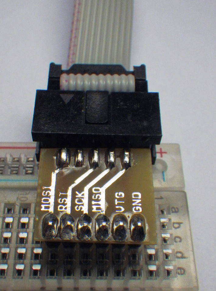
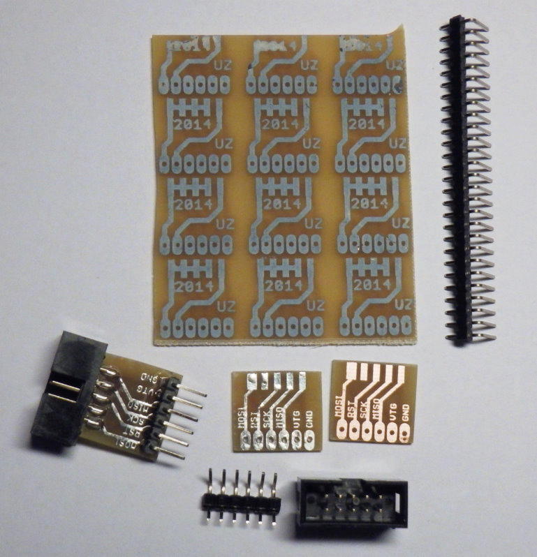
Inspired by the way the 10-pin IDC connector is mounted on the most common AVR USB programmers available on the internet, I designed my own small circuit board:
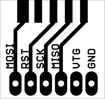
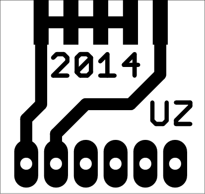
Here is the layout in the form of 1:1 PDFs:
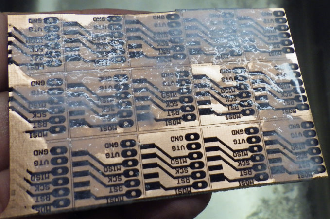
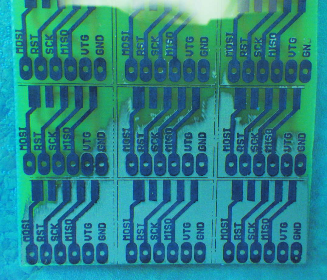
This was my first attempt to make a double-sided circuit board using the toner-transfer method. I had to realize though that the stack of two paper sheets and the circuit board did not fit through my modified laminator. Therefore I had to use a household iron to transfer the toner to the front-side and back-side copper layer at the same time. It worked quite well – aligning the paper printouts with a corner of the circuit board. I took a piece of FR4 circuit board which had place for twelve of these small adapters.
Not before I hade soldered together the first prototype I realized that I had more possibilities with this device than I had planned for:
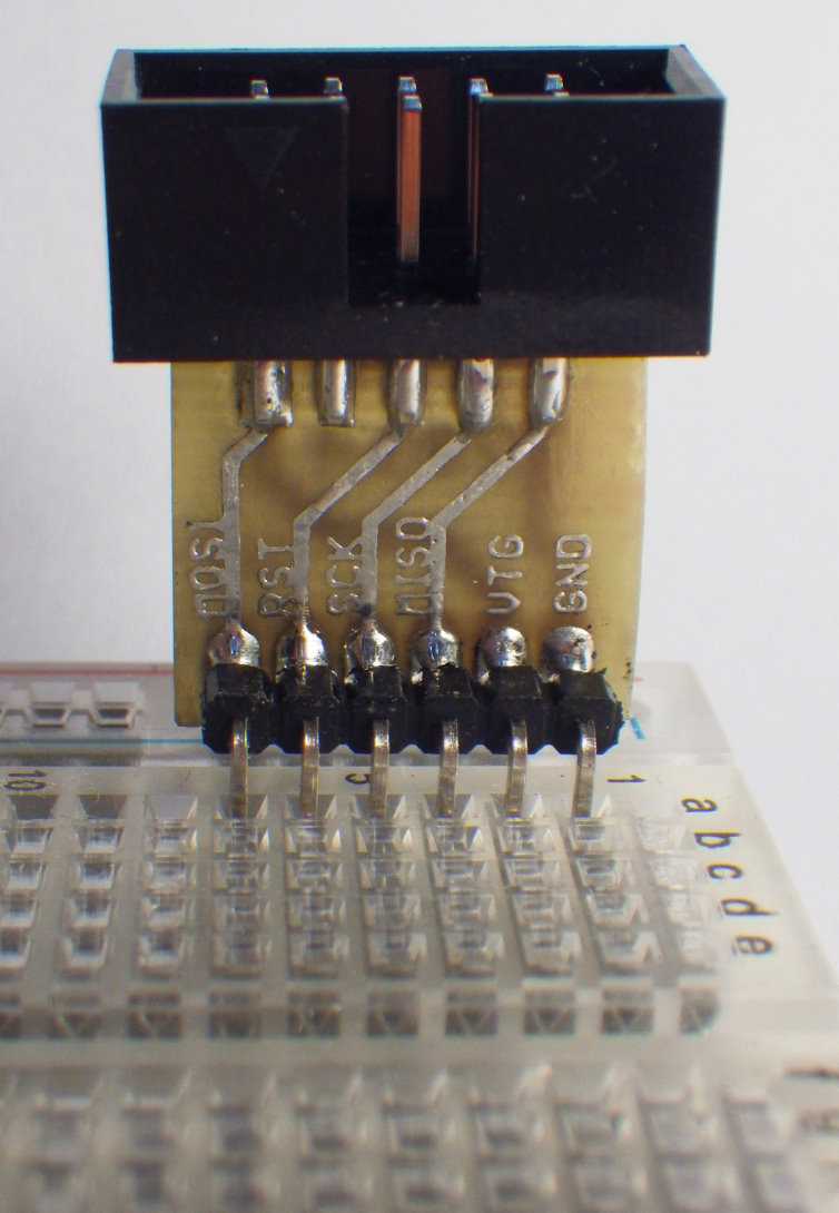
1. With a 90-degree connector towards the breadboard:
This way you will get an adapter which takes minimal space on the breadboard, since it stands vertically. However, this might introduce stress on both the breadboard and the connector itself.
The adapter will lie flat on the breadboard, with minimal stress on the board and the cable. Placing the adapter at the edge of the breadboard also takes up only a reasonable amount of real estate.
3. With a female connector:
So far I have always included Atmel’s 2×5 (or in a few cases the 2×3) ISP connector for later updates of the firmware. But routing the wires to the two rows of pins is not always an easy task – especially when trying to keep the layout single-sided. It might actually be easier to route the signals to a single row of pins – but that waits to be seen…


Pingback: An USBasp in a new design II « GreenPhotons