
Idea
You know the problem – with every new gadget comes a new remote control, and while there are programmable and universal remote controls out there, they will never just do what you want.
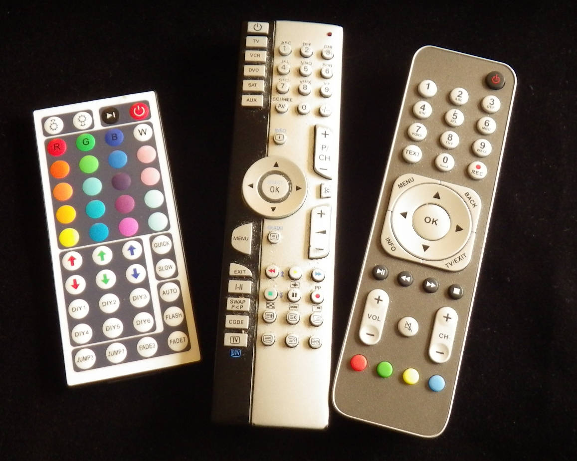
For controlling my tv, my digital box and one of the wall lights in my living room I used to have three remote controls. Each of these remotes had a gazillion buttons which I never ever use, and the ones I use regularly were partly placed at inconvenient positions. For a couple of years now I had suggested a remote control as a microcontroller project to my students, but only this year Josefine and Tobias pursued this project and gave me a proof of concept.
Libraries
There are two great libraries to give your microcontroller project access to the world of infrared remote controls, IRMP for the receiving end and IRSND for the transmitter part. While my students combined both libraries into a single, programmable unit, I only left the self learning part as an option, but went for a fixed layout of the remote until now.
Sniffer
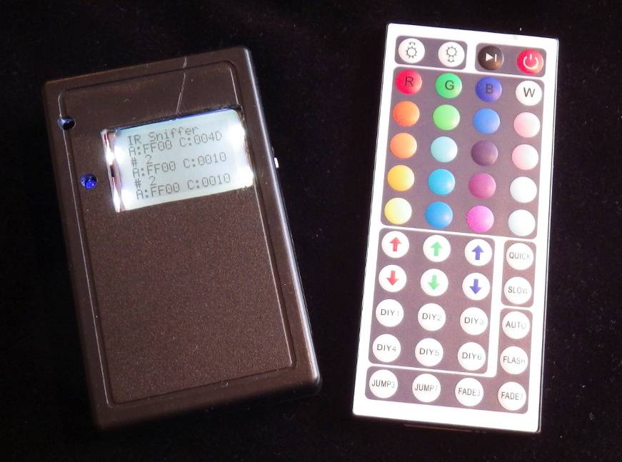
However, I first constructed a small infrared sniffer in order to acquire the codes sent out by my existing remote controls. It uses such a simple circuit that I didn’t bother to make a printed circuit board but rather copied the circuit directly from the breadboard to a veroboard.
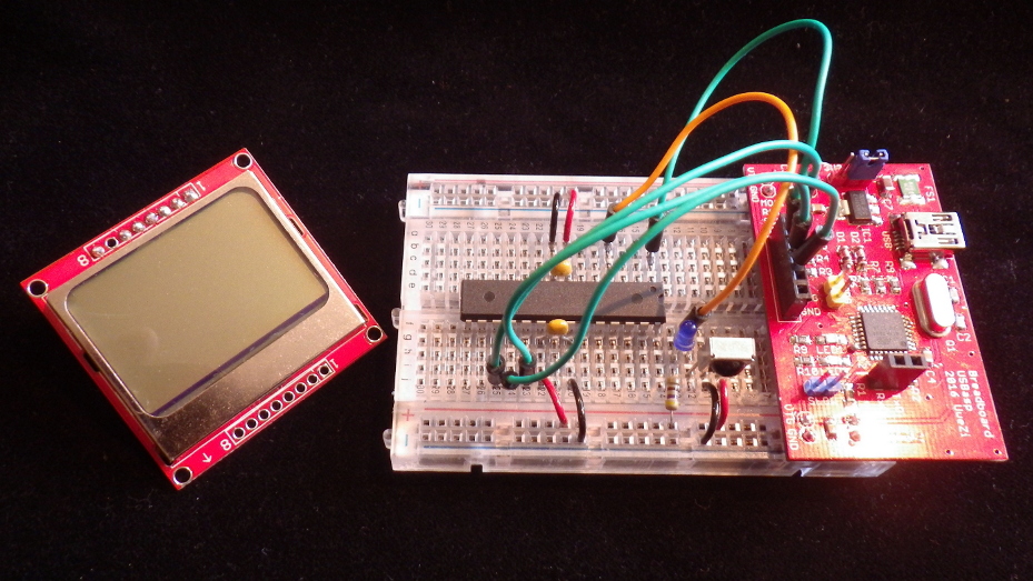
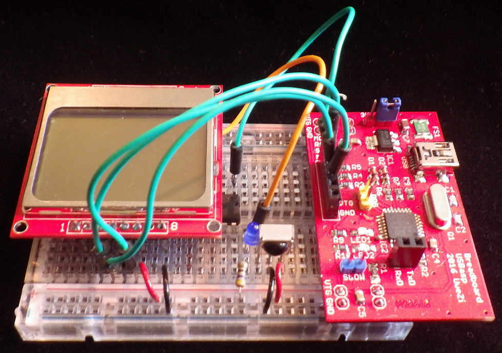
It would have been good enough to keep the IR sniffer on a breadboard, but this time I even stuffed it into a small box.
Design
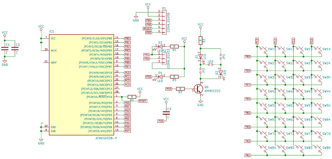
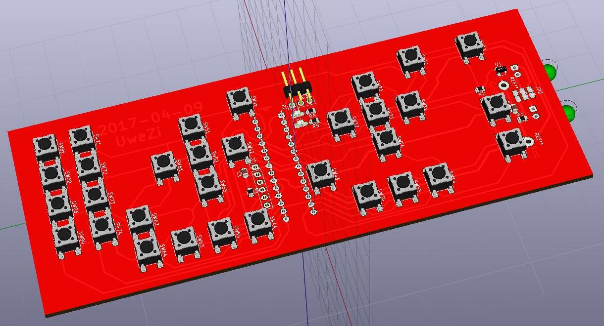
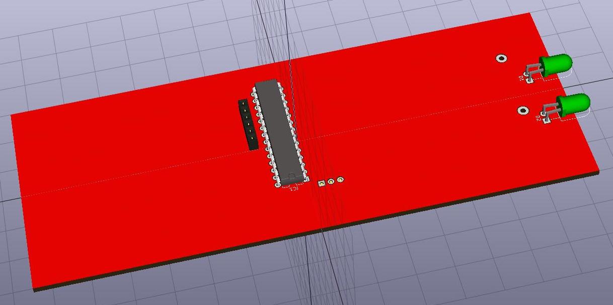
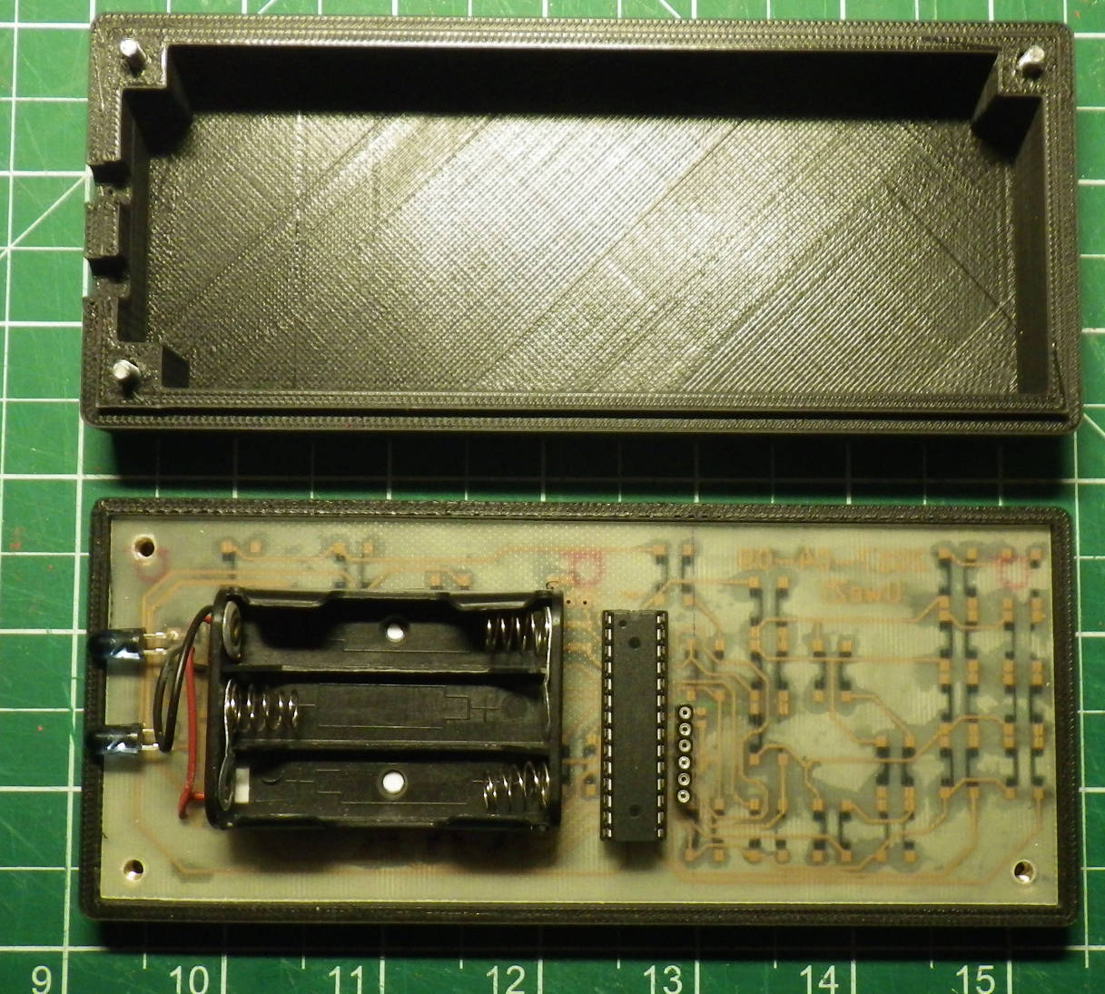
Looking at what I needed from my three remote controls I came up with 32 buttons in total which can conveniently be arranged in a 8×4 matrix – at this point I decided against the use of capacitive buttons like my students did, and opted instead for regular push buttons, and without testing anything on a breadboard first I directly went into the design of a single-sided circuit board in KiCAD. I chose to use two infrared emitting LEDs which can be either connected in series or parallel by means of jumper links – depending on the supply voltage. Since I then decided to use three AAA cells as power source, giving me nominally 4.5 V, I selected the series connected version with a 10 ohm dropper resistor in the final design.
Layout
I spent almost a day trying to make a single-sided layout around a TQFP32-packaged ATmega328 before I started over with a larger DIP28-packaged one. The biggest problem was the placement of the chip in the middle of the key matrix and still be able to route the column wires all the way through – the wide spacing of the DIP28-package makes it possible to thread the wires between two pins which is impossible for the TQFP32-package if I wanted make the circuit board using the toner-transfer technique.
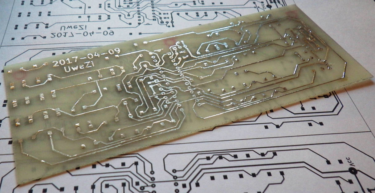
Etching
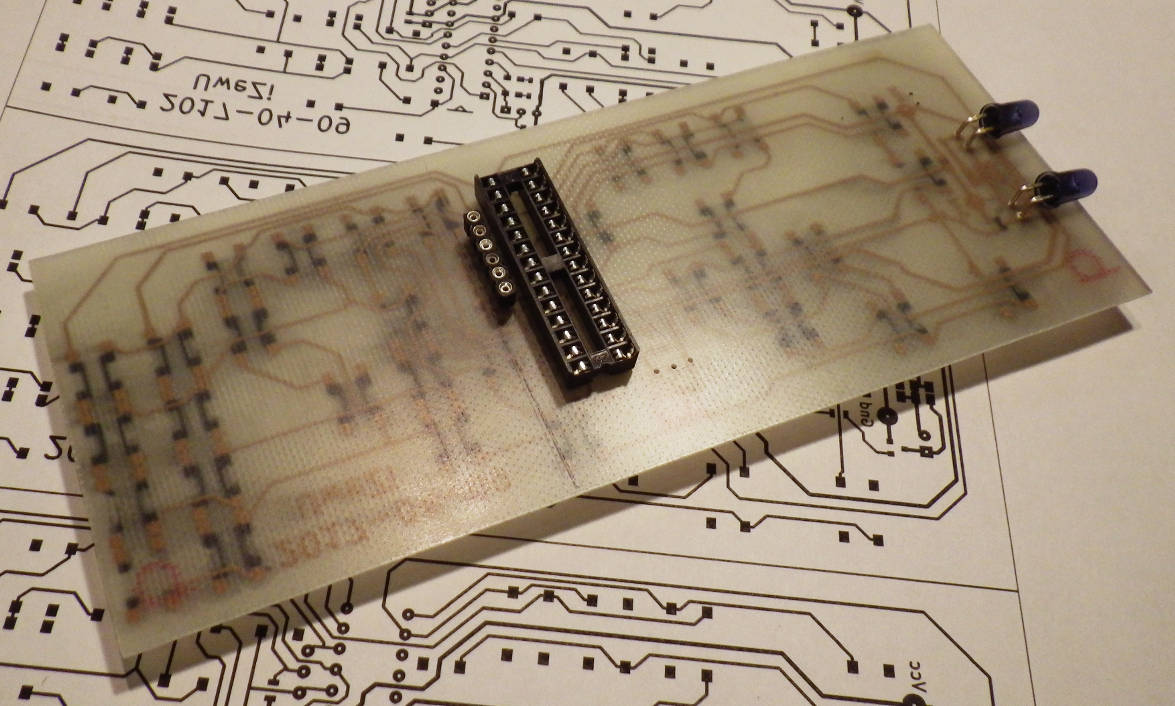
For the toner transfer process I laser-printed the mirrored pcb layout onto a sheet of glossy inkjet paper before using my modified paper laminator to transfer the toner onto a cleaned piece of copper-clad FR4 base material. After etching the circuit board then in sodium persulfate solution I trimmed the board to the exact size, drilled the holes for the microcontroller, the ISP connector and the infrared LEDs. Then I tinned the traces and soldered everything in place.

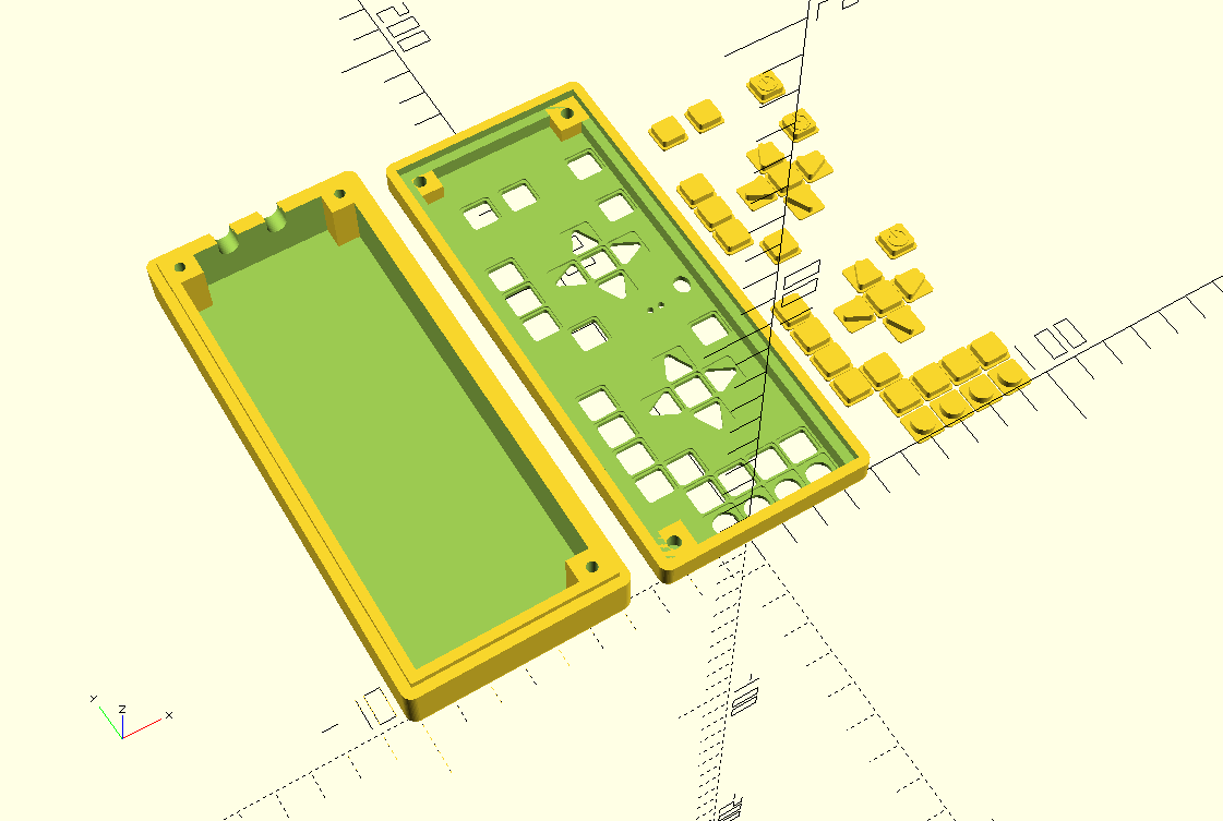
Designing a case
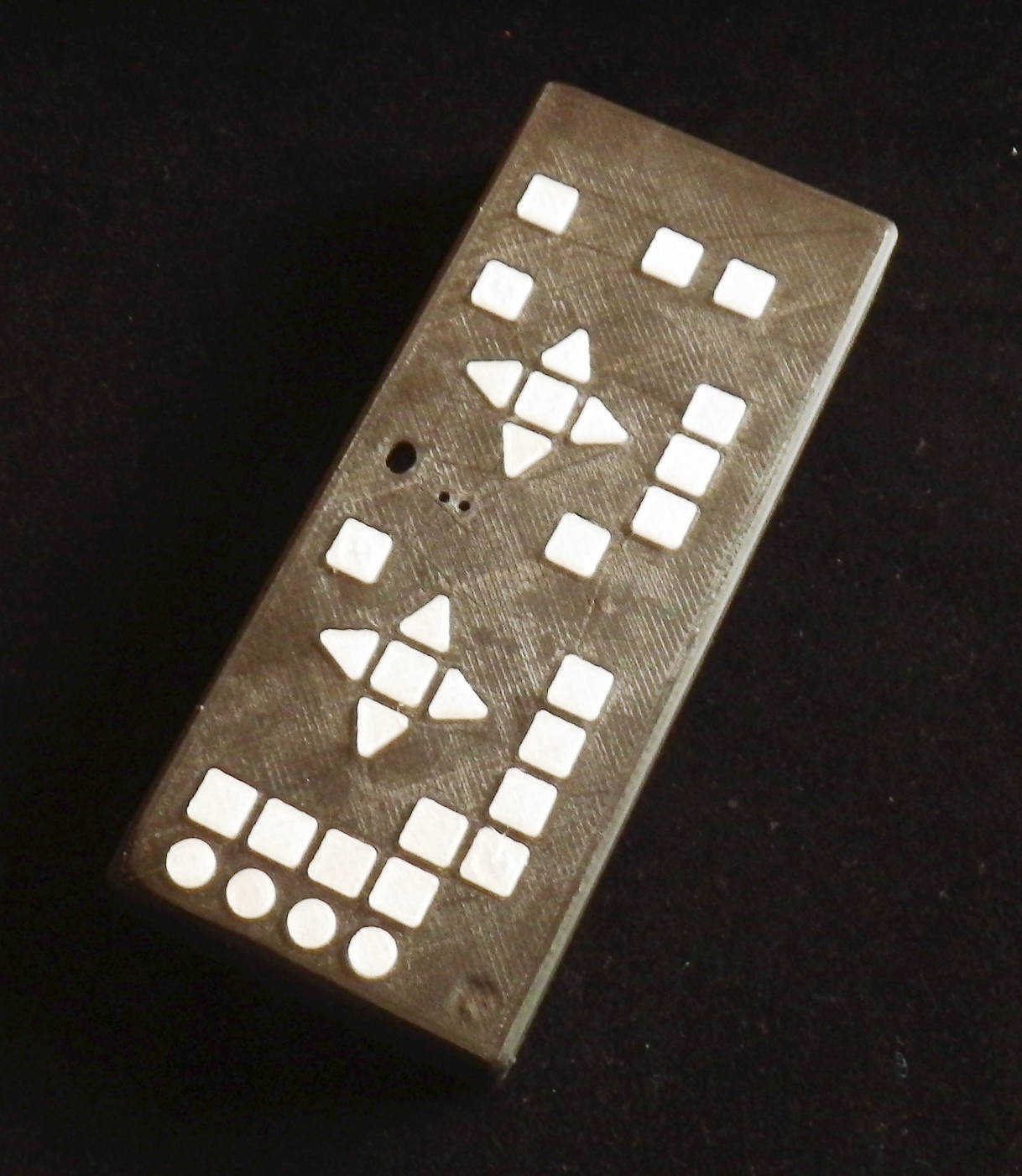
The final touch was of course to make a matching case for the remote – I did this using the parametric engine of OpenSCAD, before slicing the file in Cura and printing it on my Wanhao Duplicator.
So here it is then, The outer front is still a bit blend and I am still thinking over the best way to label the individual keys.
Performance
- yes, it works nicely!
- the microcontroller is kept in sleep mode, from which it wakes up with a pin change interrupt when any button is pressed
- peak current through the LEDs is about 150 mA
- standby current consumption of the remote control is about 70 µA
Bill of materials
- 1 pc Atmel ATmega328P
- 2 pcs TSUS5400 IR LEDs
- 1 pc MMBT2222A NPN transistor
- 32 pcs 6 mm x 6 mm 4-pin smd push buttons
- 1 pc 0805 ceramic capacitor 4.7 µF
- 1 pc 0805 ceramic capacitor 100 nF
- 1 pc 0805 resistor 10 ohm
- 1 pc 0805 resistor 10 kohm
- 3 pcs 0805 resistor about 470 ohm
- 1 pc 0805 blue LED
- 1 pc 0805 red LED (optional for self-learning)
- 1 pc TSOP4838 IR receiver (optional for self learning)
File download area
- AVR GCC source files for the IR sniffer 20170327_m328p_irsniffer
- AVR GCC source files 20170410_m328p_ir_remote
- KiCAD files 20170409_remote_kicad
- OpenSCAD files 20170410_remote_scad
2020-07-14 UPDATE
A couple of days ago I had to change the batteries in the remote for the first time after about 3 1/4 years, at a continues current draw of 70 µA this corresponds to a total charge of 2 Ah, quite ok for a set of AA alkaline batteries including their self-discharge.