


Every place in our course laboratory is equipped with an analog oscillsocpe and a Metex Universal System. This instrument consists of a power supply with two fixed and a variable outpur voltage, a multimeter, a function generator and a frequency counter. This sounds nice and it usually is – most of the time the instrument works satisfyingly for our experiments, but there are some disadvantages and most of all it’s not student proof.
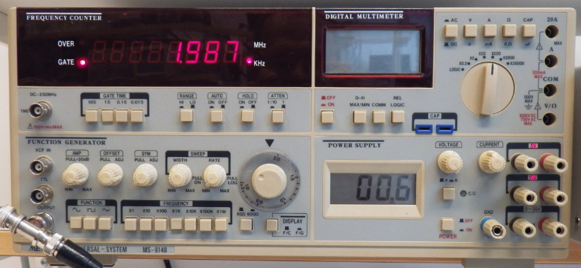
Metex MS-9140 Universal System.
First there are several models with somewhat different features – mostly it is the frequency counter and the multimeter which differe between models. The apparently newest series is equipped with green LED displays which are impossible to read, because the company Metex was cheap on a green filter in front of the display. We solved this issue in our lab with pieces of green plastic foil – at a cost of practically nothing, but it makes you wonder if any engineer from Metex has ever been trying to sit in front of the instrument.
Then there is the multimeter. The whole instrument is connected to the power line and its functions powered from internal power supplies – everything but the multimeter. That one is powered by a 9V-battery which is located inaccessibly on the back of the instrument. I thought I knew the reason and assumed the multimeter was based in the standard voltmeter circuit ICL7106 which has the disadvantage that it cannot measure with reference to its own ground potential. The simple way would then have been to just move the whole circuitry from a handheld multimeter (and Metex has become a big company just by making these kinds of multimeters) into the big box, including the battery. The other possibility would have been to use a dc/dc converter which would have added a cost of a few dollars.
As I wrote, I thought I knew. But no… According to the Service Manual the internal multimeter is based on a MAX134 which is well capable of measuring with reference to its own ground potential, and as another matter of fact the display of the built-in power supply is based on the ICL7106 which is powered from a separate winding of the transformer. So WHY?
Finally to today’s problem which triggered this post. One student group ran into problems when they connected their function generator to their self-built transistor amplifier. Just when they connected the function generator the sine curve on the oscilloscope showing the output of the function generator flatlined: But they were sure that their amplifier circuit was ok -after all, that’s what they built themselves… With 20 other groups in the lab at the same time they took the function generator (a 20kg box) from the unoccupied neighboring place and connected it up – and it showed the same misbehavior – what a stupid course lab with all this broken equipment. Before they got to the third function generator I came by – they told me of their problems with the broken equipment, but I became suspicious that there should be such an assembly of broken equipment in just this corner of the lab. I checked their circuit, which connected the +15V supply of the transistor directly to its input and from there of course into the output of the function generator. The broken ones actually smelled slightly badly from their ventilation openings…
If Metex had included a fuse in the output of the function generator it could have been student proof – now I wonder if we can add this feature by ourselves and upgrade these instruments.
Latest Comments